Korg MonoPoly - Modifications
ATTENTION: THESE MODIFICATIONS REQUIRE TO OPEN THE CASE OF
THE MONOPOLY. THIS SHOULD ONLY BE DONE BY PEOPLE, WHO KNOW HOW TO
HANDLE THE DANGEROUS VOLTAGES INSIDE OF THE SYNTH PROPERLY WITHOUT
ENDANGERING THE LIFE OF OTHERS OR THEMSELVES!!! IF YOU DON'T HAVE THE
REQUIRED EXPERIENCE - KEEP YOUR HANDS OFF!!! DOING THE WRONG THINGS
INSIDE AN ELECTRICAL INSTRUMENT MAY KILL YOU OR PEOPLE, THAT RELY ON
YOUR WORK. I WARNED YOU. I REJECT ALL LIABILITY FOR ALL CONSEQUENCES OF
THE FOLLOWING INSTRUCTIONS!
- Disable the reset of the keyboard algorithm when switching in FX-Mode
- Disable the reset of MG2 when playing a new chord in arpeggiator mode
- MIDI input and MIDI clock for the arpeggiator (MIDI interface from CHD servis)
- V-Trigger to S-Trigger converter for the external
arpeggiator clock (either built-in or as adaptor cable)
- Higher speed range, adjustment of the lowest speed, and various range settings for MG1
- Various speed settings for VCF EG and VCA EG
- Selectable modulation range for the VCF EG
- Select between MG1 or VCO4 as modulation source provided by
the modulation wheel
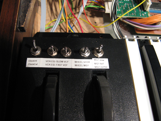
The switches at the bender panel. From left to right:
|
Modifikations on KLM-356
(CPU-board)
Disabling the reset of key assign mode when switching to effects mode
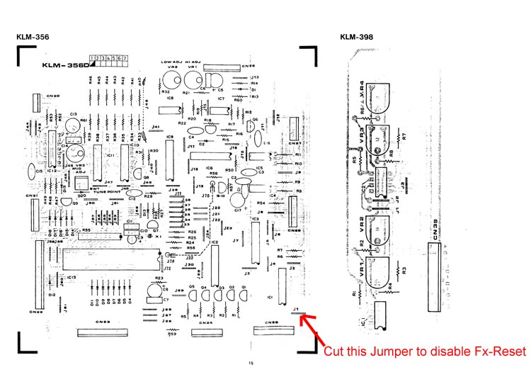
If you enable the so called effects (hard sync and crossmodulation), then the key assign mode is resetted to unisono-mode. This is often unwanted, especially if you use the chordmemory or the arpeggiator in poly mode with different VCO settings and want to extend these to sync or crossmodulation. If you want to disable this simply cut the jumper J1 on the uP/Arpeggiator board KLM-356.
V-Trigger
to
S-Trigger
Adapter
for
the
Arpeggio
Clock
 |
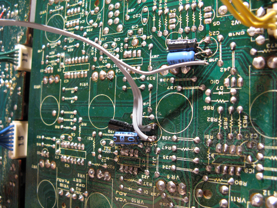
If you have your MonoPoly MIDI-fied with the MIDIKit from CHD-Elektroservis then you have to use an adapter cable like described in the picture above. If you have a standard MonoPoly, then you may add the resistor and transistor on the pcb KLM-356:
- switch off the Monopoly and remove the powerchord from the wall outlet
- open the frontpanel screws (if not done yet): four at the bottom rear side and two on each front side.
- Remove four screws which hold KLM-356
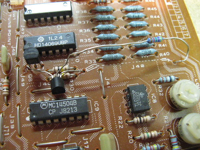
- Unsolder the cable J42 which runs from the upper boarder to the center of the pcb
- Solder a 10k resistor to the solderpoint of J42 near R40; do not cut the legs of the resistor. You will need nearly the full length
- Solder the transistor (any NPN 2N3904 or BC549) with its emitter (usually the right leg if you look at the flat side) to the other solder point of J42
- Solder the collector (left leg) of the transistor to the left leg of transistor Q8
- Solder the basis (center leg) to the open end of the new resistor.
- Now mount back the PCB again to the synth, close the lid, switch the synth on and test with a V-Trigger.
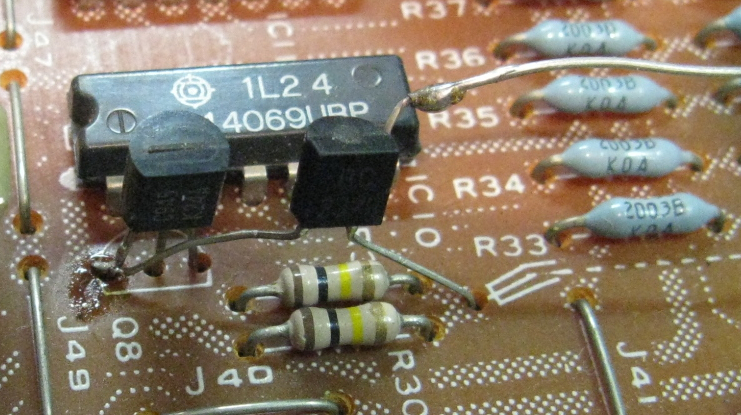
The left transistor is the original Q8, the right one is the new transistor.
REMARK: These pictures are intend only to show the connection of the base of the transistor. Do not bend it really that way.
Also in the final solution the legs of the resistor should be cut to a suitable length and the whole resistor should be mantled in a heat shrink tube.
Modifications on the KLM 353
(LFO and Bender board)
To make those modifications you have to unmount the LFO pcb: - switch off the Monopoly and remove the powerchord from the wall outlet
- open the frontpanel screws (if not done yet): four at the bottom rear side and two on each front side.
- remove the knobs for master volume, bender depth, mod wheel depth, waveform MG1, speed MG1 and speed MG2.
- remove the screw aside the arpeggio latchmode switch
- remove all nuts from the potentiometers and the waveform switch.
- now the pcb will be free.
Disabling clock-reset of arpeggio in internal clock-mode
With internal clock the Arpeggio-clock from MG 2 restarts with every new chord. I did not like that and wanted to play the arpeggio in a continous beat, so I removed C7 on Board KLM 353. This takes away the reset pulse from the MG2.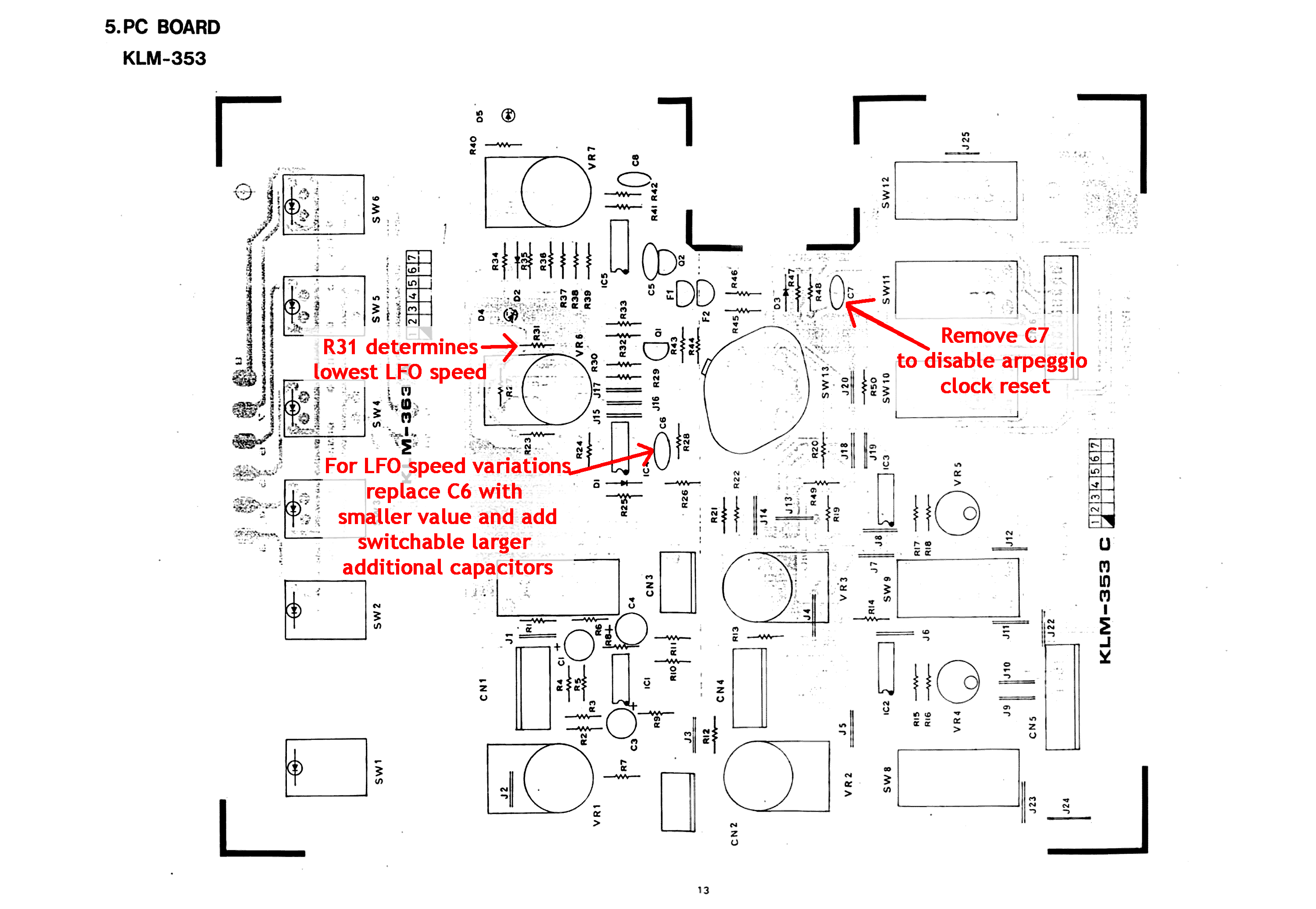
various speeds for MG1
There are several reasons to modify the speed control of the modulation generator. I really like Modulation generators with a high frequency. Especially using them for filter modulation opens a field of vowel and voice sounds. On the other hand the MG1 of the MonoPoly is not very reliable on very low speed settings. I know at least two MonoPolys, which suffer a "freezing" MG1 at extreme low speed setting. So I decided to modify the two parts which determine the frequency of the MG1: Capacitor C6 defines the basic center frequency which is modified by the potentiometer which is formed by R23, VR6 and R31. C6 is replaced by a 2.2 nF. Via a single pole double throw switch with center off (on-off-on) the original 0.1uF or a 10uF electrolytic cap can be added parallel. To prevent the the freeze at the extreme low frequency R31 is increased from 47Ohm to 220Ohm.
How to...:
- Remove the KLM353 as described above
- desolder C6 but keep it a hand
- solder a 2.2nF capacitor in the location of C6
- desolder R31
- mount the pcb again to the frontpanel.
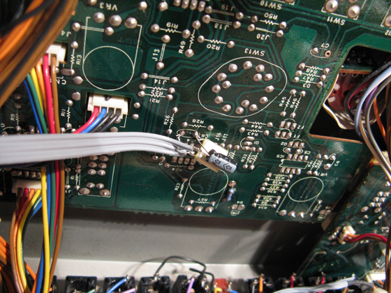
- on the solder side of the pcb solder the original 0.1uF and a 10uF with one leg to one of the solder points of C6 (but both caps to the same solder point).
- connect each of the open ends of these two capacitors to the outer pins of a on-off-on SPDT-switch.
- connect the center pin of this SPDT-switch with the other solder point of C6.
- Solder a 220Ohm resistor on the solderside of the pcb to the solder points of R31. You may experiment with the best value. It may vary from 47Ohm to 1kOhm. It is more a matter of taste and also a matter whether your MG1 stops at extreme low frequencies. If it stops make R31 larger. If it does not stop the leave it at the original value.
Modifications on KLM-355 (Filter VCA-Board)
To make those modifications you have to unmount the VCF/VCA pcb:- switch off the Monopoly and remove the powerchord from the wall outlet
- open the frontpanel screws (if not done yet): four at the bottom rear side and two on each front side.
- remove all knobs right from the VCO-volume knobs.
- remove all nuts from the potentiometers
- now the pcb will be free.
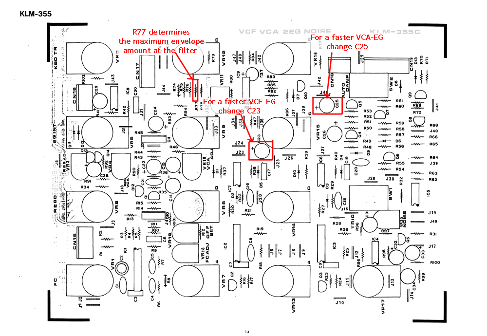
Change the envelopes speed and characteristics
The potentiometers for the envelope times attack, decay and release cover a very large range. From quite short values at ~15 ms to several seconds. Korg had to trade this wide range with two disadvantages. The characteristic of the loading and unloading times have in the beginning a nearly linear slope then change to the known exponential curve and then get more linear again. If the proportion between the time determinating capacitor and the loading/unloading variable resistors is changed then the curve concentrates more on the exponential part of the curve (this is mathematically spoken not correct, but it explains the problem better).Also the short times, which are interesting for faster sounds of modern electronic music are covered by the first 10% of the potentiometer range, while the other 90% cover longer times, which I typically never am using. As it is quite impossible to get potentiometers with different values and characteristics, which would suite mechanically, I decided to simply change the time determinating capacitor. This has finally the same effect. To keep the chance to still have longer envelope times, I made this capacitor switchable - similar to the one for MG1 speed described above.
Also I wanted to have a more detailled resolution of smaller envelope modulation amounts at the filter. So I made the related resistor R77 switchable to two different values.
- Remove KLM-355 from the frontpanel as described above
- Desolder R77, C23 and C25. Remember the orientation of the capacitors. Don't loose them - we will need them later again.
- Solder an electrolytic capacitor with 0.47uF or 1uF into the place of C23 and C25. Watch out for the right orientation of the caps. There is a "+" "marking on the pcb. The capacitor has a stripe with "0" on it. The leg which is closer to this "0"-stripe must be soldered to the hole not marked with "+".
- Solder a 100K or 120K resistor in the place of R77 (don't worry for its orientation) (*see remark at the photo below)
- Remount KLM-355 to the frontpanel again
- Now solder the original C23 (and C25) with the positive leg (not marked with "0") to the original solderpoint marked with "+" "(but this time from the soldering side of the pcb). Watch out for the right orientation!
- Connect the negative leg (marked with "0") to one pole of a simple on/off-switch.
- Connect other pole of the switch with the other original not marked solderpoint of the capacitor on the pcb. Since both capacitors are connected to ground it is enough to use one wire back to the pcb and solder this wire to both switches.
- Solder a 100K resistor with one leg to the original solderpoint of R77 on the soldering side of the pcb (which one does not matter) (*see remark at the photo below)
- Connect the other leg of the transistor to one pole of a simple on/off-switch. (*see remark at the photo below)
- Connect other pole of the switch with the other original solderpoint of R77 on the pcb. (*see remark at the photo below)
- You're done.
The two capacitors for each envelope. I did not solder the new smaller capacitor from the component side, but also from the soldering side. This made it easier to change between different values for evaluation.
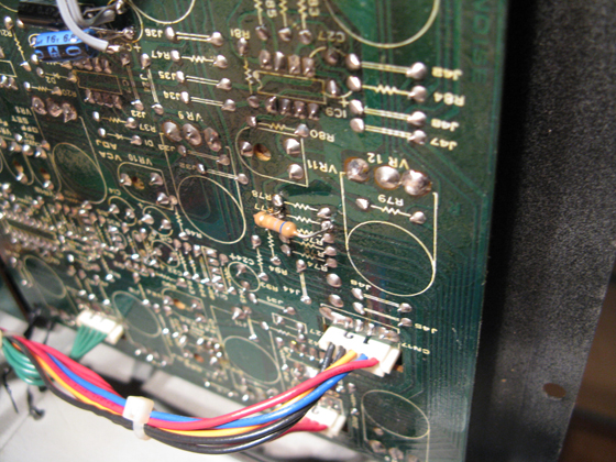
The resistor R77 for the VCF EG Modulation amount. As you can see, I did not add a switch, but I am satisfied with a single value.
MIDI-In for the Korg MonoPoly
There are several MIDI-kits for the Korg MonoPoly available:- CHD Elektroservis from Czechia offers a MIDI-Kit. For more details please visit their site: http://www.chd-el.cz/index.php?id=409. In opposite to the original instruction I did not feed the MG1/Clock-In signal to the CHD interface board. Instead I added a switch, which selects between the MG1/ArpClock-In signal and the clock signal from the MIDI interface. So I can change the clock setting without the need to send control data.
- A more advanced MIDI-Kit is the firmware rewrite from Tubbutec, the ModyPoly. The Tubbutec extension not only adds MIDI-In and MIDI-Out, but also adds several playmodes and arpeggiator modes. The ModyPoly can be used in the MonoPoly and in the Polysix.
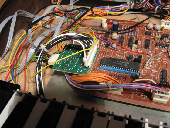
The CHD MIDI interface seated on the CPU pcb.
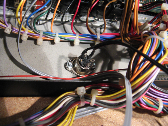
I mounted the MIDI socket below the Jack board.
MIDI-Out for the Korg MonoPoly
MIDI-Out can be achieved either by the mentioned interface from tubbutec or by a Doepfer CTM64. I did this already with my Moog Prodigy but not yet with the Monopoly.Replace the SSM2033 VCO by a CEM3340
The SSM2033 VCO chip is quite an unobtainium. Thankfully Tauntek.com provides a PCB that holds a CEM3340 and some additional parts and so replaces the original chip. See http://www.tauntek.com/MonoPoly.htmThe following modifications are planned or in developement stage, but not yet finished, or simpley not documented.
- VCO 4 as alternative modulation source for the modwheel
(filter cross modulation).
- separated triggering of envelopes
- monophonic arpeggio CV/Gate out
- polyphonic CV and GATE out.
- (polyphonic vcf/vca. This would be basically possible using an Poly61 voiceboard, but I dropped this plan after I had acquired an Polysix.)