Building
Instructions - VMC-1
!!! PRE RELEASE DRAFT Hardware!!!
This is a preliminary manual. It is based on prototypes only. Requirements of the final hardware may cause changes in the described feature.
Preliminary:
I will not explain soldering. This kit is not really difficult to solder, but I do not recommend it as a first project. The order of the soldering is important. Some parts will hide the solder points for other parts. If you mount the parts in the wrong order, you will lock out yourself from finishing the module. Also I strongly recommend to obey the mounting instructions for the sockets and potentiometers with the help of the frontpanel.Requirements and tools:
- a clean work bench with good illumination
- soldering iron 25W-30W; if possible a soldering station with temperature control
- tin-solder; the PCBs are lead free. Of course lead free tin solder is nice for the environment, but mixed lead/tin-solder is much easier to handle, and it is still allowed to non professionals (at least in the EU)
- electronic side cutter or microshear like the "Knipex Electronic Super Knips"
- midsized combination pliers
- midsized side cutting pliers
- screw driver with 3mm blade
Not necessary but helpful:
- a 2cm strip of clear adhesive tape (used for mounting the LED)
- a "helping hand" pcb holder
- a bending jig made from a strip board pcb:
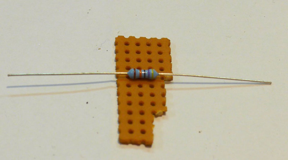
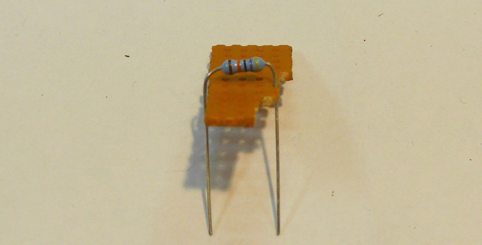
All parts on the pcbs a designed for this standard grid.
Overview:
Basically we will solder parts in the order of their heigth. As mentioned above some parts will hide the solder points for other parts. So keep the following order:- First the rear side.
- resistors and diodes
- trimmpotentiometer
- sockets for the arduino (see remarks in the detail section)
- voltage regulator
- capacitors
- pinhead rows
- dil-switch
- power socket (optional)
- Then the front side.
- momentary switches (see remarks in the detail section)
- 3,5mm sockets(see remarks in the detail section)
- display (see remarks in the detail section)
- potentiometers (see remarks in the detail section)
- Then mount the frontpanel
- LED (see remarks in the detail section)
Details REAR SIDE
Resistors
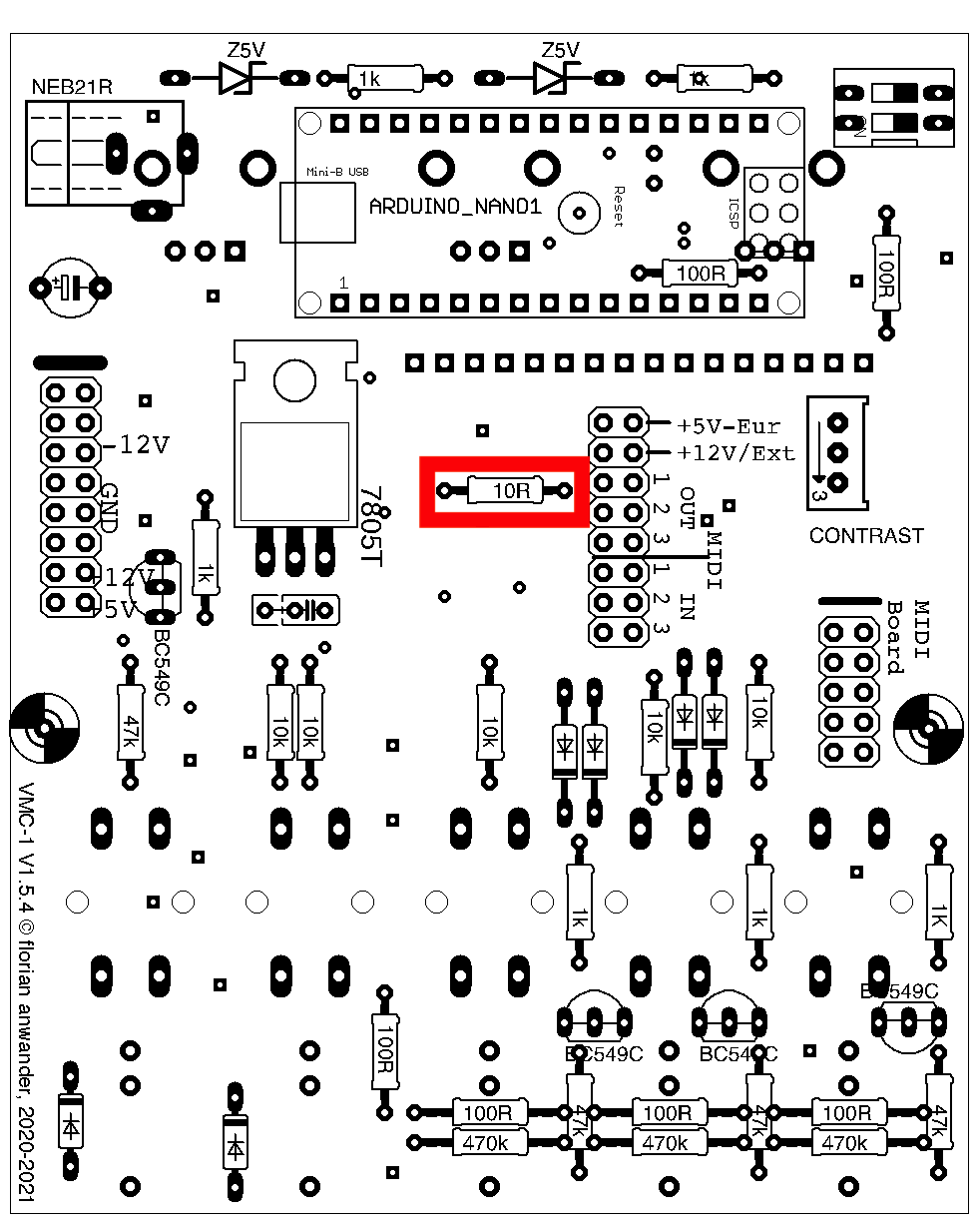
The resistors may come in two different physical sizes (0.3W and 0.6W). The wattage does not matter for the functionality (with one exception!). It is simply a question, which size was available while buying. I prefer the larger 0.6W types, but sometimes only the smaller ones are available.10 Ohm:
This resistor controls the brightness of the display backlight; so it has influence on the power consumption of the module.If you don't have to care for the power requirements then, simply use a wire instead of this resistor. You may use a wire that you have cut from some other resistor. The display backlight will be pleasing bright.
This resistor MUST be of the 0.6W type!
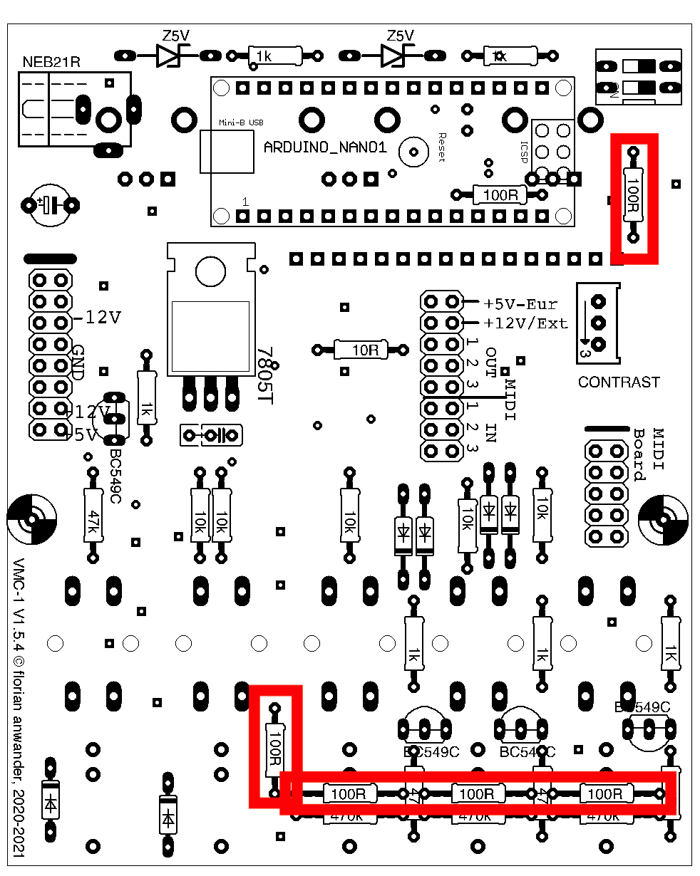
100Ohm:
These 100 Ohm resistors are optional. They are used to separate the incoming ground from the local ground. I found that to be very helpful to suppress groundloop caused hum. My software for the VMC-1 takes those resistors in account. If you transfer other software, like software that was written for the MIDI-Shield, then you have to adopt it to the slightly different minimal voltage.These should be soldered before the 47k resistors!
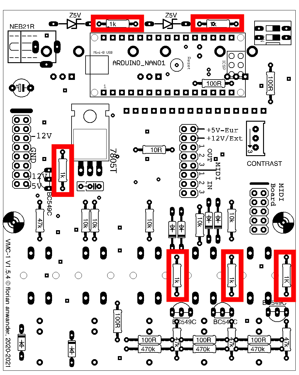
1kOhm:
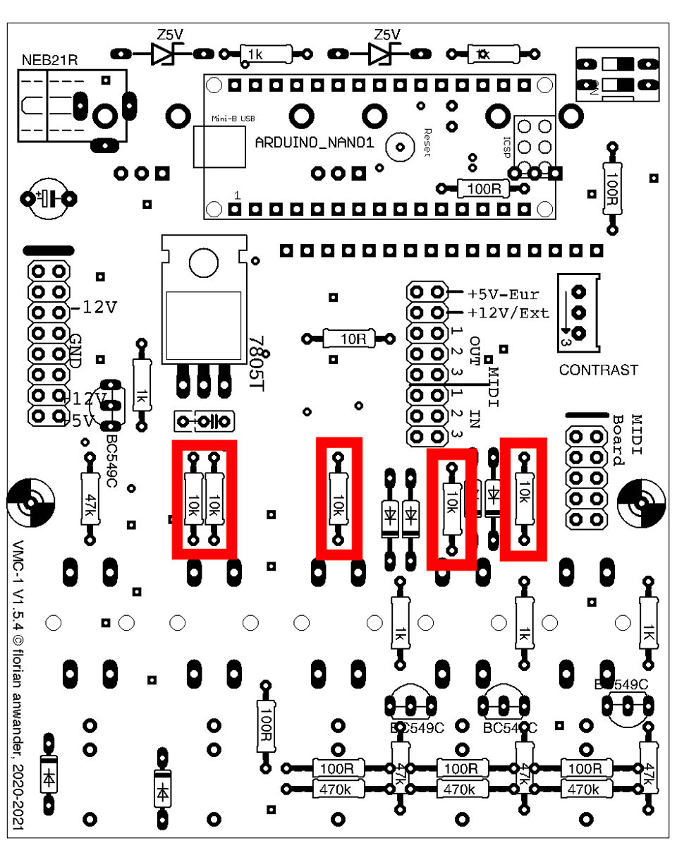
10kOhm:
470kOhm:
These should be soldered before the 47k resistors!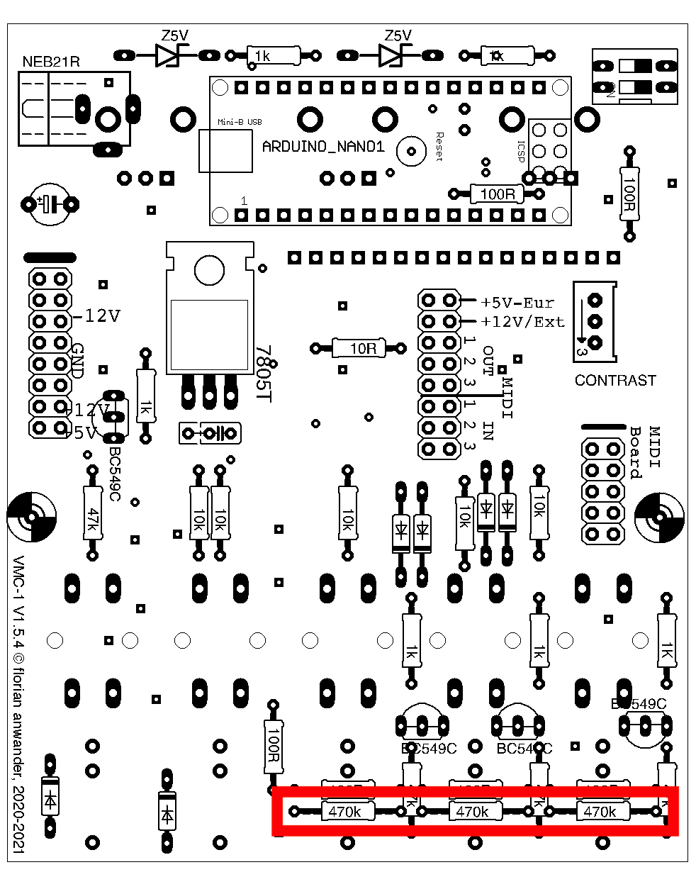
47kOhm:
These should be soldered after the 100R and the 470k resistors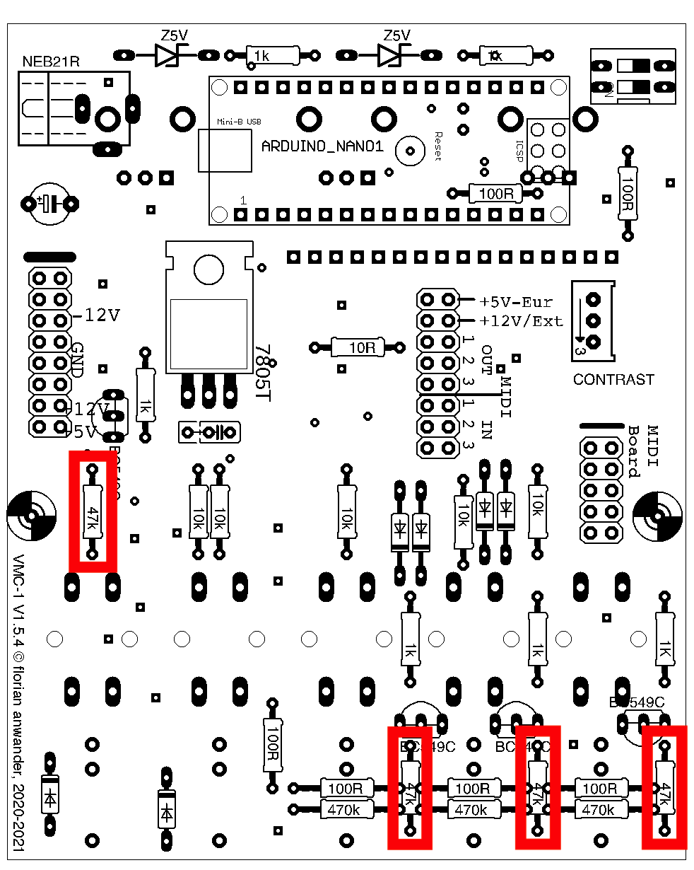
DIODES
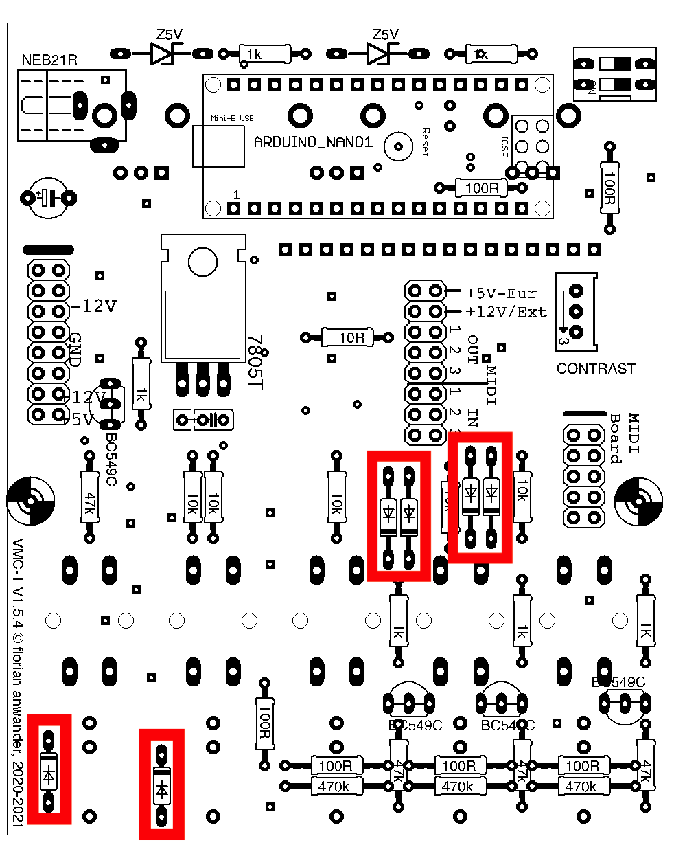
The diodes are a little difficult to distinguish. The devices name is printed on both of them but if your eyes are like mine, then you will need a magnifier.Diodes have to be placed in the the right orientation. There is a black ring around the glass body. It must point in the same direction as the black mark is on the pcb diagram.
1N4148
you will find written1N
41
48
on the glass body
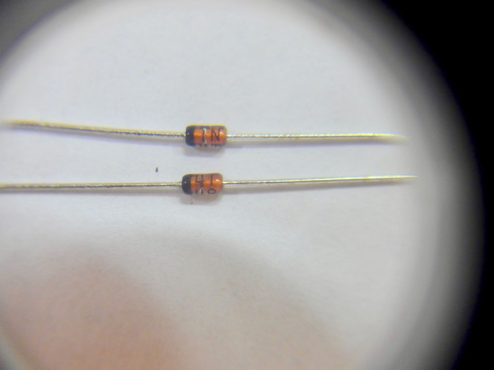
Click on the image to enlarge.
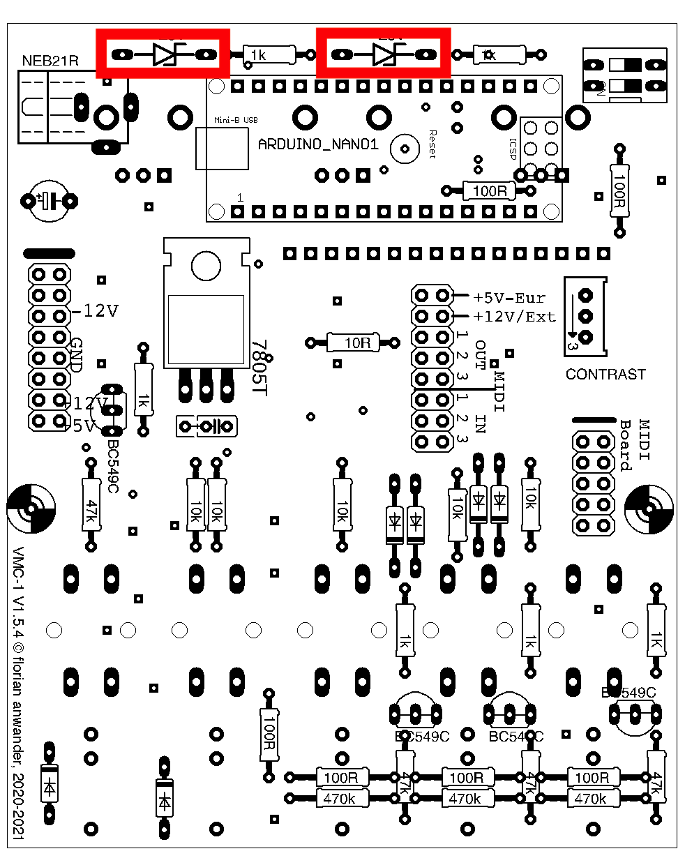
Z5V1:
You will finde a "5V1" written on the glass body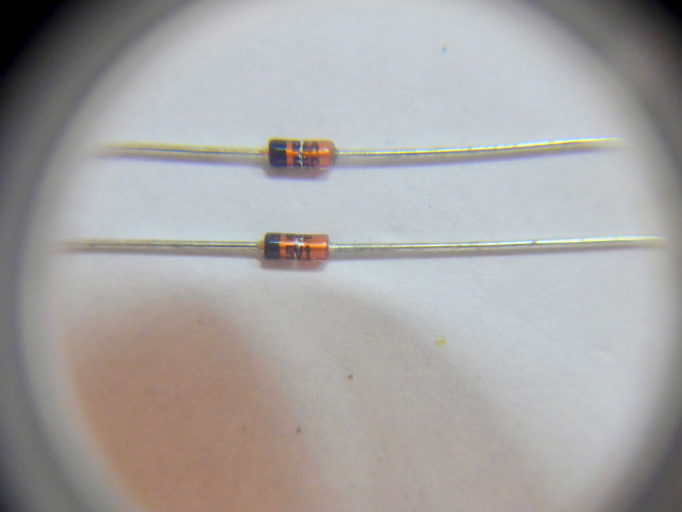
Click on the image to enlarge.
The black ring on the glass body must point to the right.
Voltage Regulator
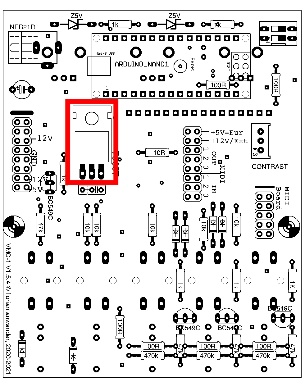
You have to bend the pins of the regulator IC in a 60° angle:
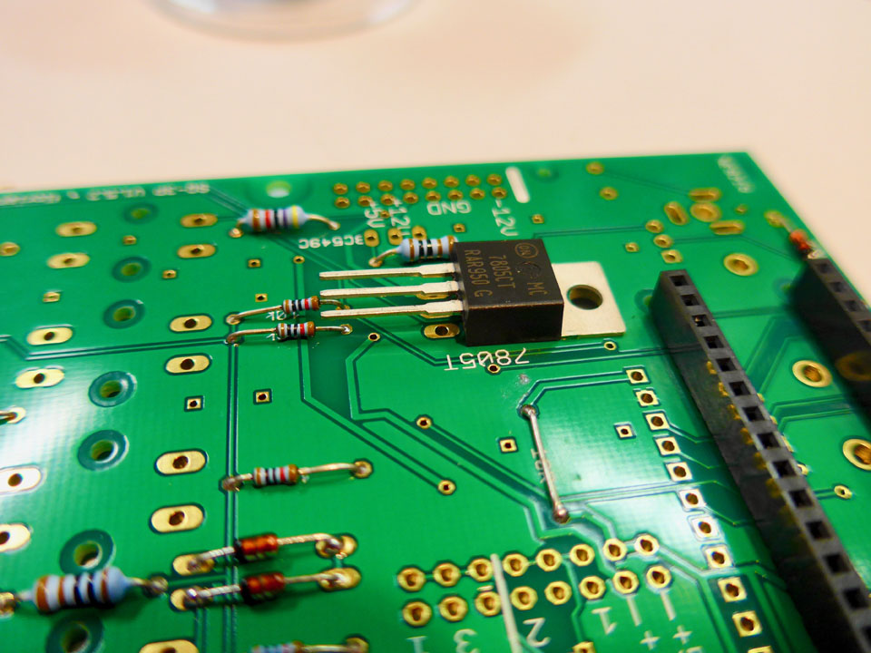
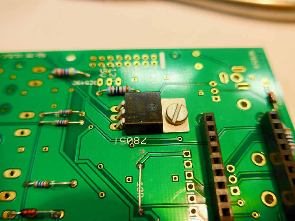
The mounting screw shown in the pictures is optional; the pcb will take up the temperature of the IC a little better, but this will not replace a heat sink. If you want to use this 5V regulator for other modules in the your system too, then mount it standing upright and add a heat sink to it (not included in the kit or in the parts list).
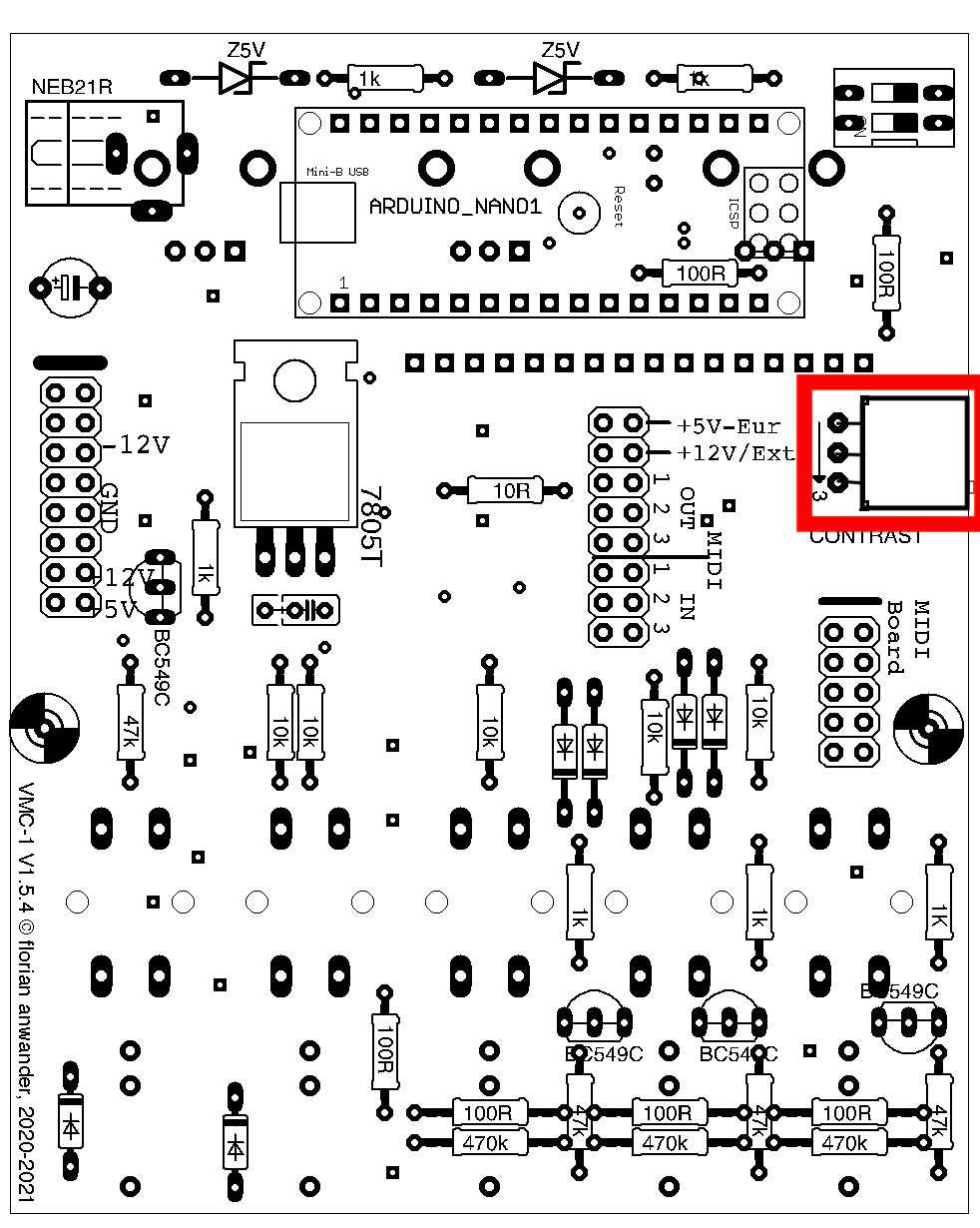
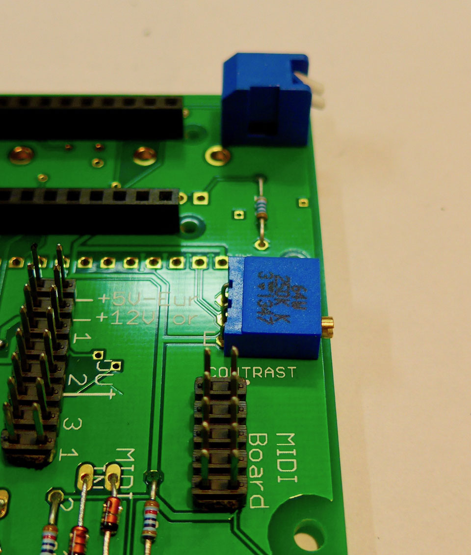
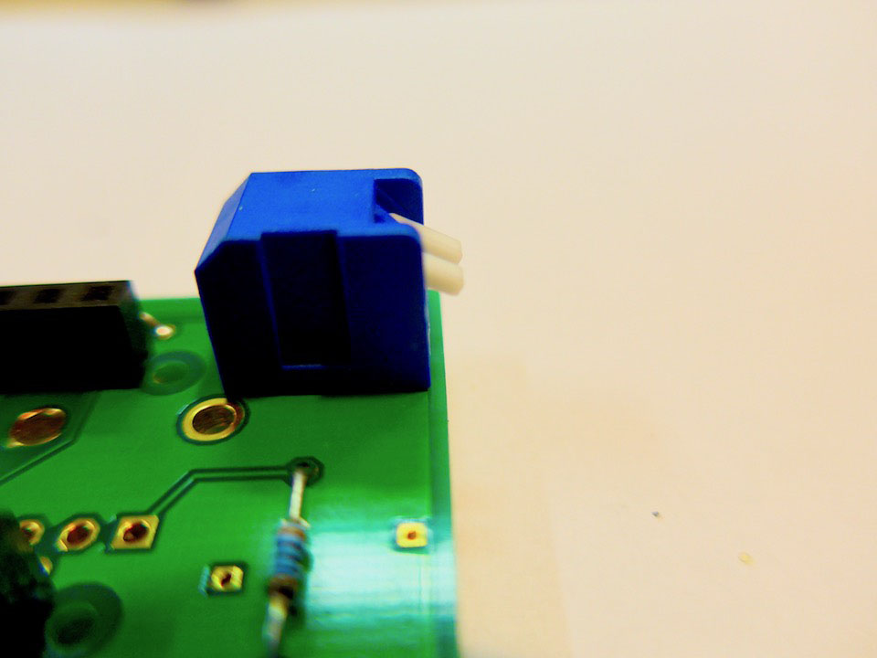
Trimmer
The Trimmer comes with legs for upright mounting. You have to bend the legs 90 degrees to mount the trimmer horizontally: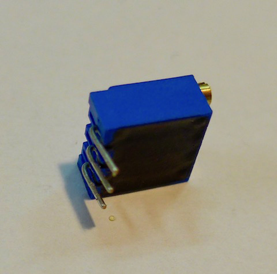
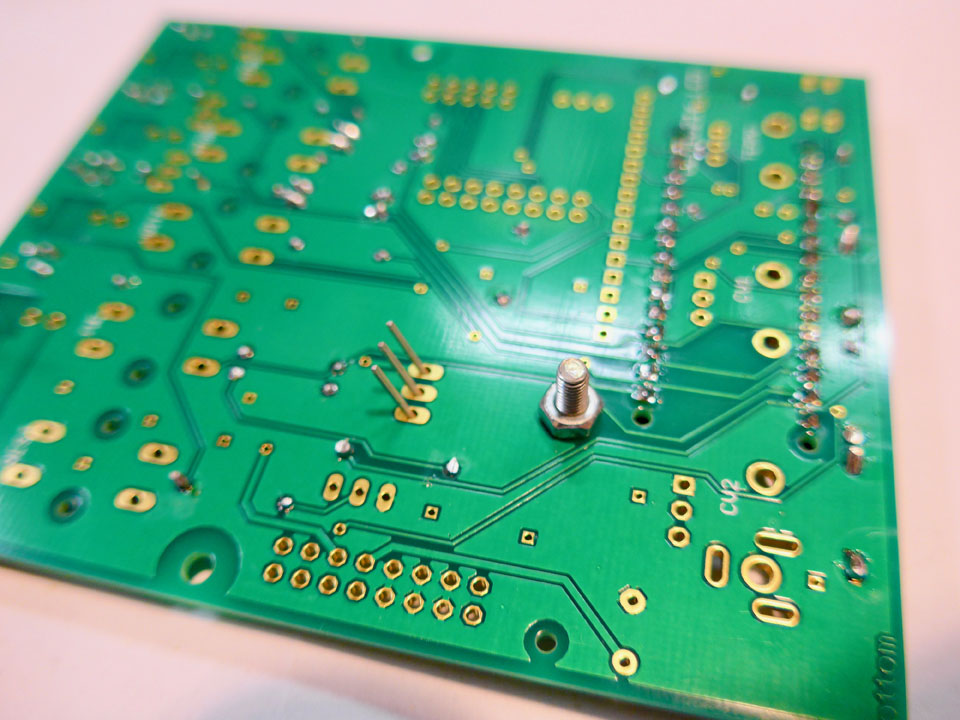
Socket rows for Arduino
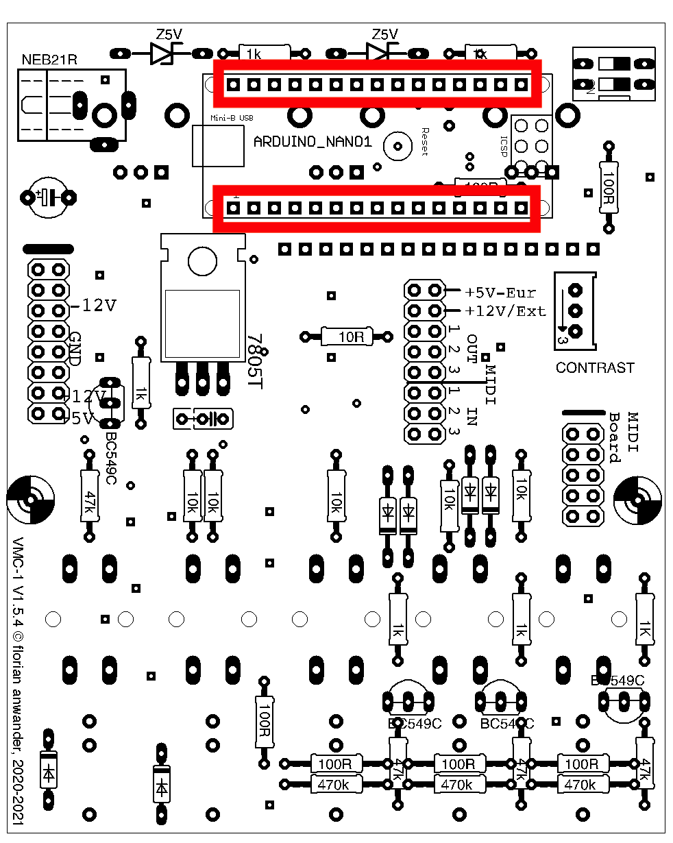
The sockets must be placed really vertically. They tend to fall over to either one or the other side. You can urge them to stand really upright with a simple trick: while soldering insert the 2x8-pinheaders across the sockets and remove the pin headers afterwards.
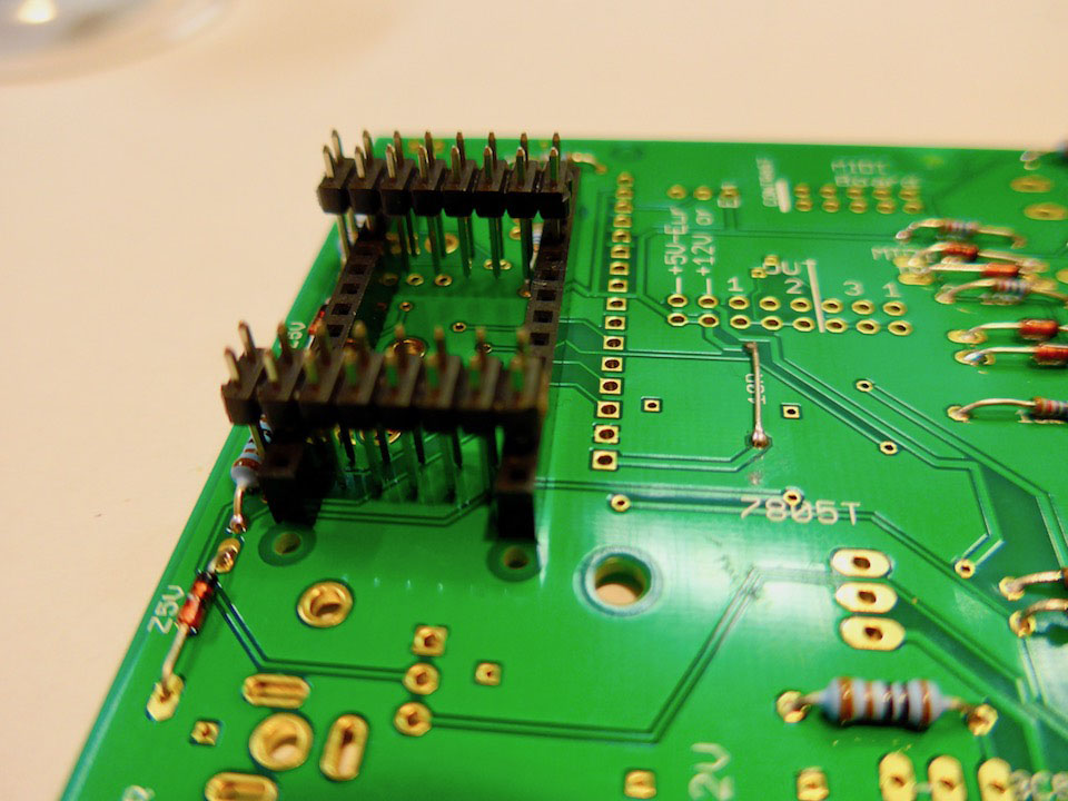
I advise against using the Arduino itself for this task!
Transistors
BC549C
Keep the orientation of the transistors in mind. On of the three transistors at the sockets "looks" into a different direction!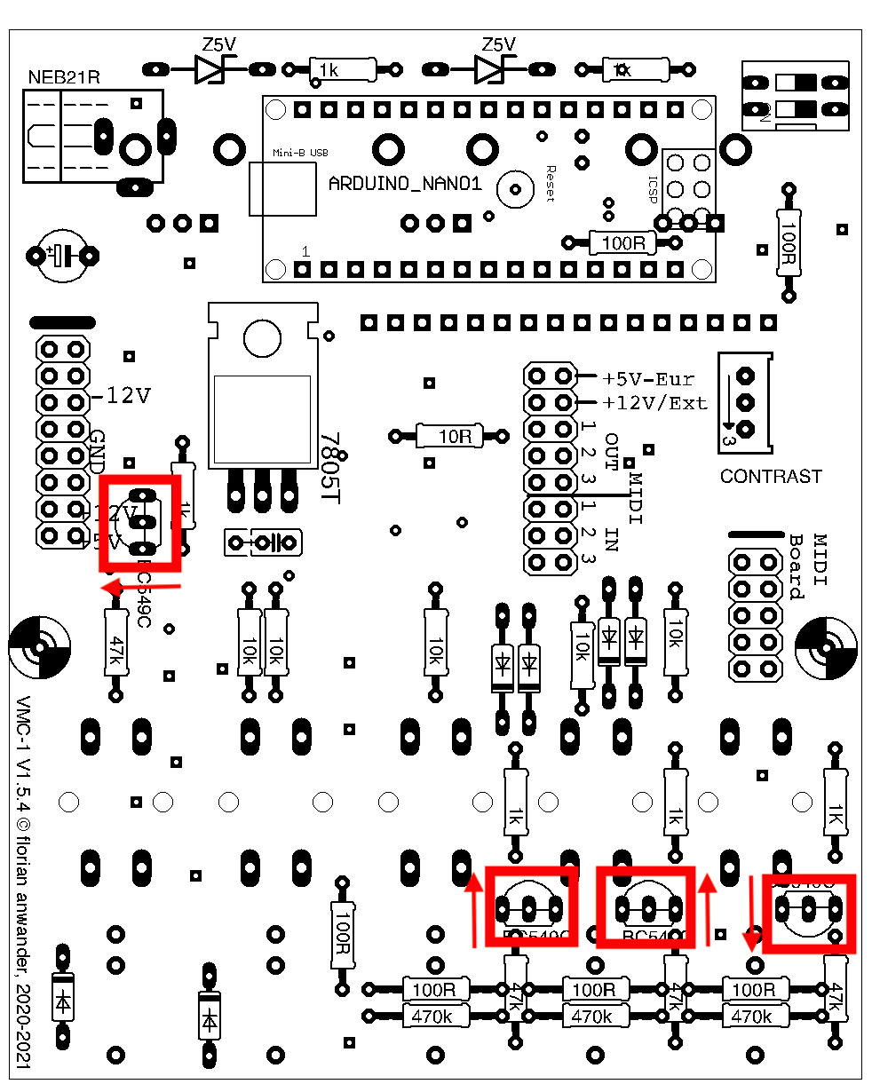
I recommend to solder the center pin of the transistor first, and then the outer pins.
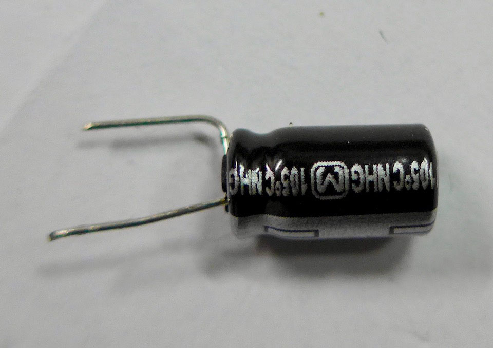
Capacitors
There are two capacitors. One round electrolytic capacitor (short "elco") and one rectangular foil capacitor. Obey the orientation of the elco.Depending of the body style of the elco its legs must get bent:
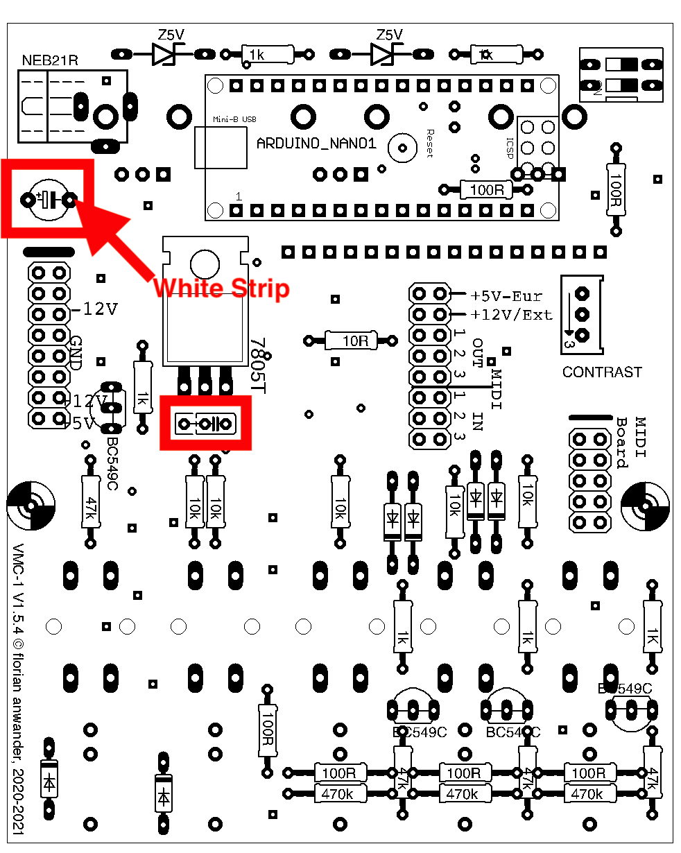
Also the outer dimensions may be so large, that it is not possible to connect the USB cable, if the capacitor is soldered in vertically. In this case I recommend to mount the electrolytic capacitor in a lying position:
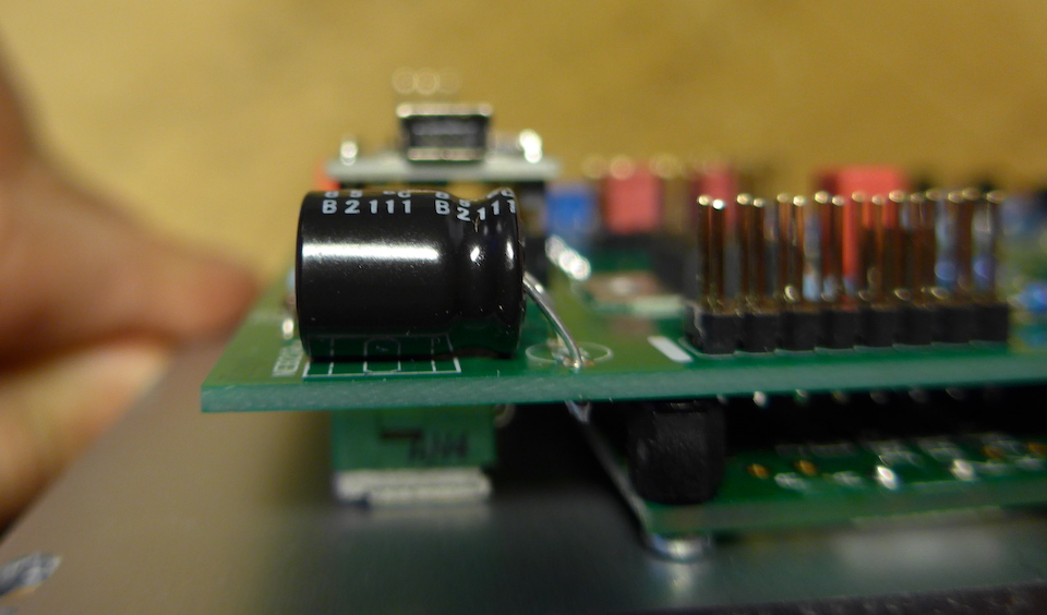
The white(or light grey) strip on the electrolytic capacitor must point to arduino socket.
The foil cap may come either with narrow legs or wide legs. The pcb is designed for both variations. If your kit contains the variation with the narrow legs the cap has to be placed at the most right possible position:

DIL-Switch
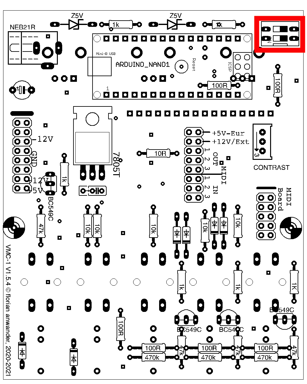
The ON-position (required for the regular operating mode) is pointing down
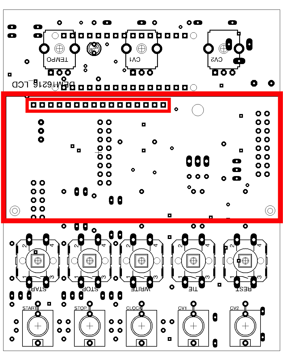
Pinheaders
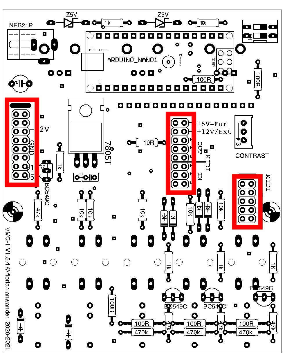
Powersocket
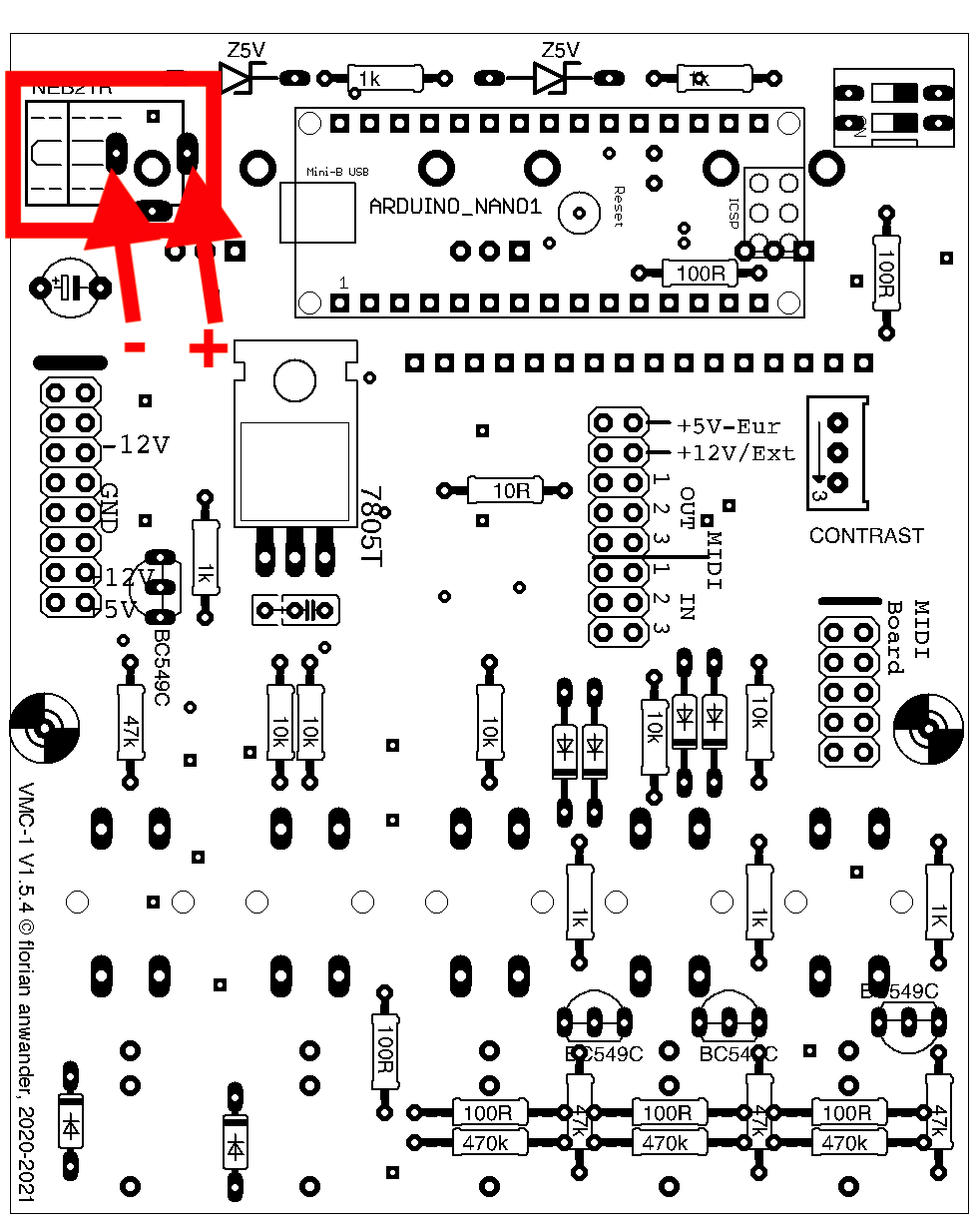
The pcb is prepared for a power socket. Using this you may run the VMC-1 as a standalone device with an external 9V-DC wall wart. I found that I never use this powersocket on the pcb, but usually I use a separate power socket in the housing of the device. So I do not deliver the socket anymore. Instead the following picture shows where to solder the plus and the minus lead coming from the external power socket.If you want to use the socket on the PCB: it is a "Lumberg NEB21R".
If you want to use an external socket I recommend the "Lumberg 1614 19"
That's it for the rear side!
Details FRONT SIDE
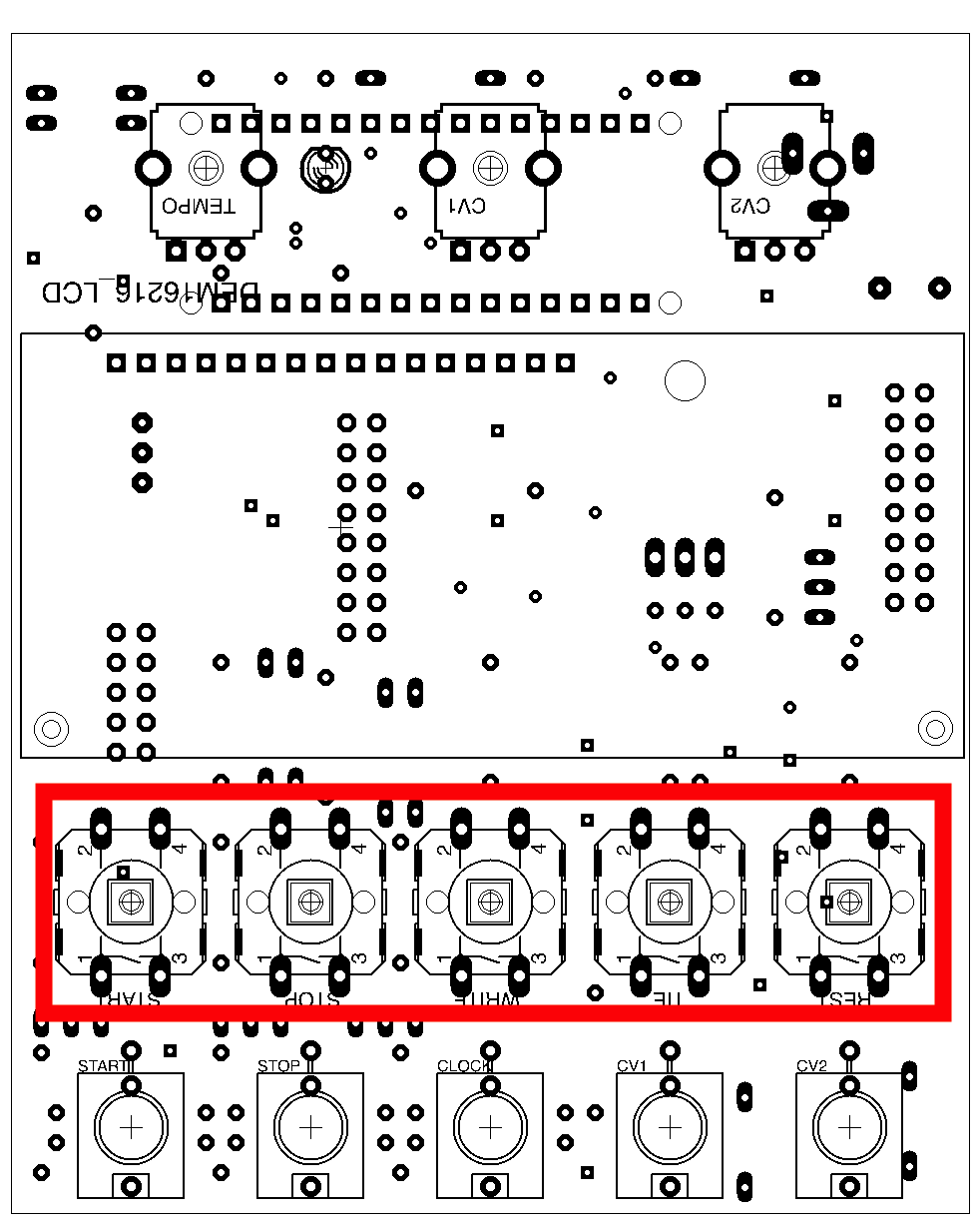
Momentary switches
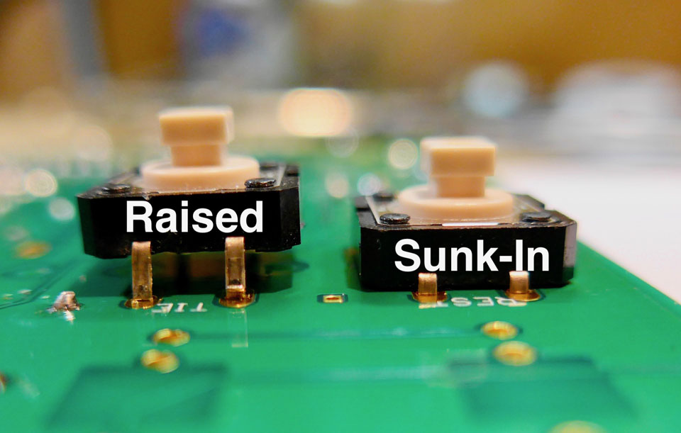
For the momentary switches there are two possible positions in relation to the front panel: sunk-in or slightly raised.

You may be used to the raised position from other modules. The sunk-in position avoids unwanted actuation and is equally in handling (to my opinion).
If you want the raised position then seat the switch only on the pcb, without pressing the contacts through the pcb. Then solder the contacts on the front side on the pcb (same side as the switch is placed).
If you want the sunk-in position then seat the switch on the pcb and press it through the pcb. Then solder the contacts from the pcbs rear side
Sockets
Place the sockets on the pcb and solder only one pin of each socket: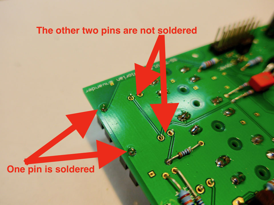
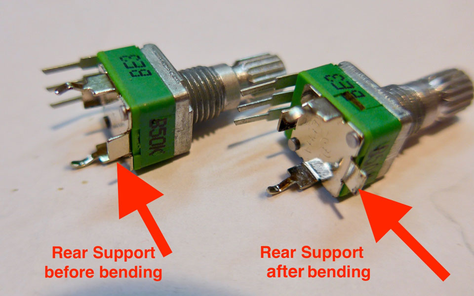
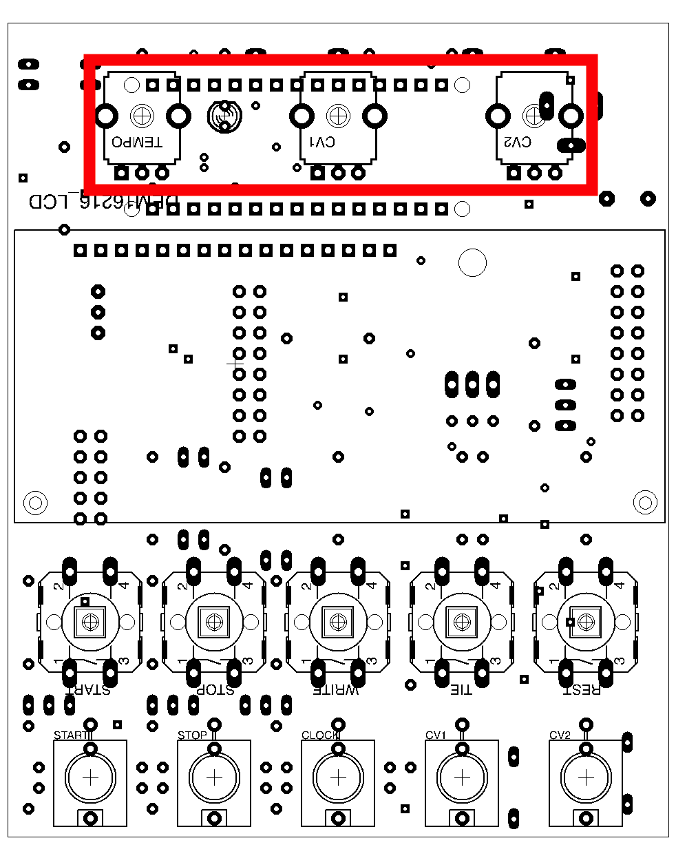
Potentiometers
Mounting the potentiometer on the pcb is the most tricky part of this kit.First you have to bend the rear support for 90 degrees:
Then place the potentiometer on the pcb. You will see that the metall bottom of the potentiometer is very close to the pins of the socket row for the arduino.
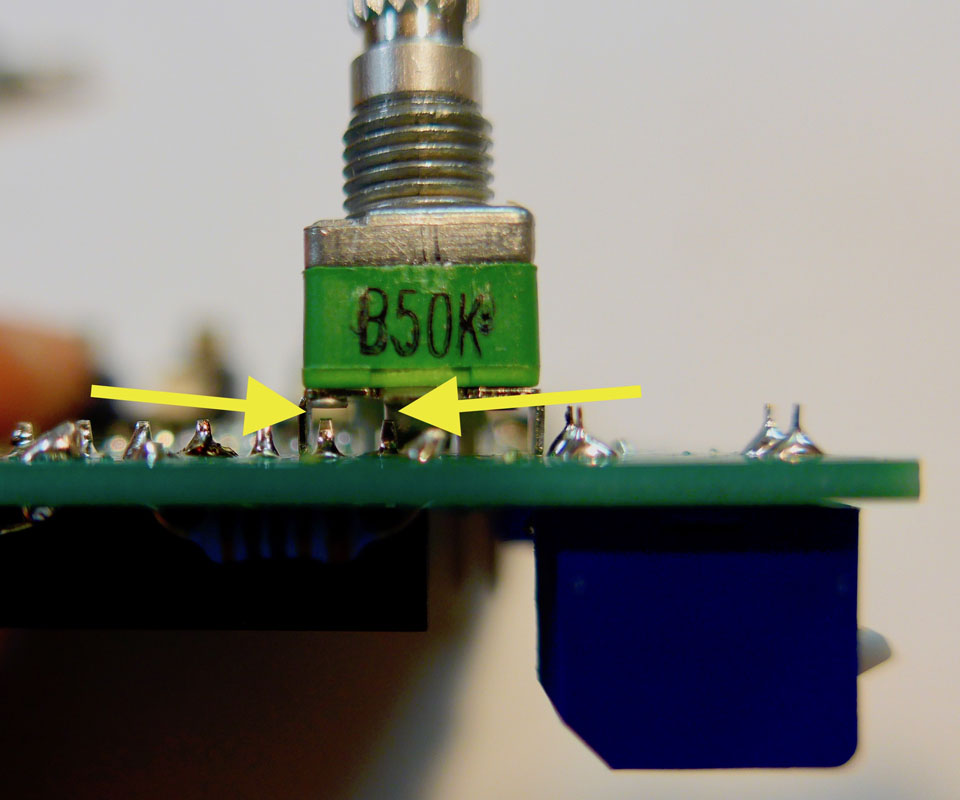
Now cut the corresponding pins with the micro shear or the side cutter pliers
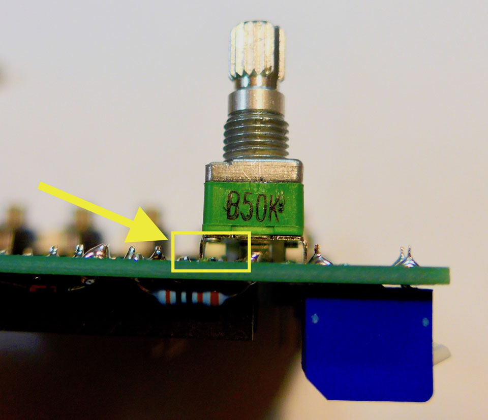
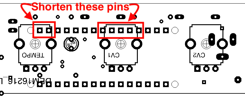
Finally solder the middle pin of the potentiometer. Do NOT solder the other pins or the mechanical clamps.
Display
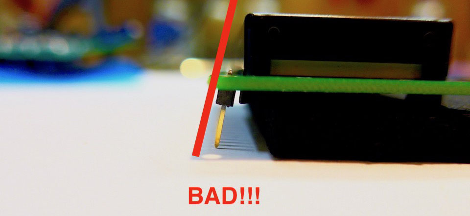
There are four black spacer blocks. Mount them to the pcb of the display with the M2.5x4 screws (the picture shows only two of them):Now place the single row pin header in the VMC-1 pcb and place the display on the pinheader. Fasten the lower end spacers on the VMC-1 pcb. Don't worry: There are really only two holes for it in the pcb! It is not a mistake. Now the pin header should sit rectangular in the LCD pcb:
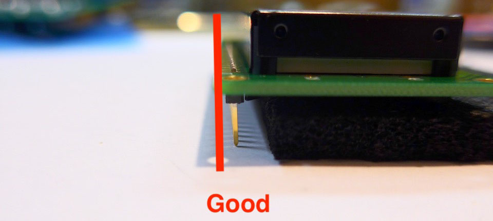
Solder the pin header to the display pcb.
Then turn the complete module to the other side and solder the pin head to the pcb
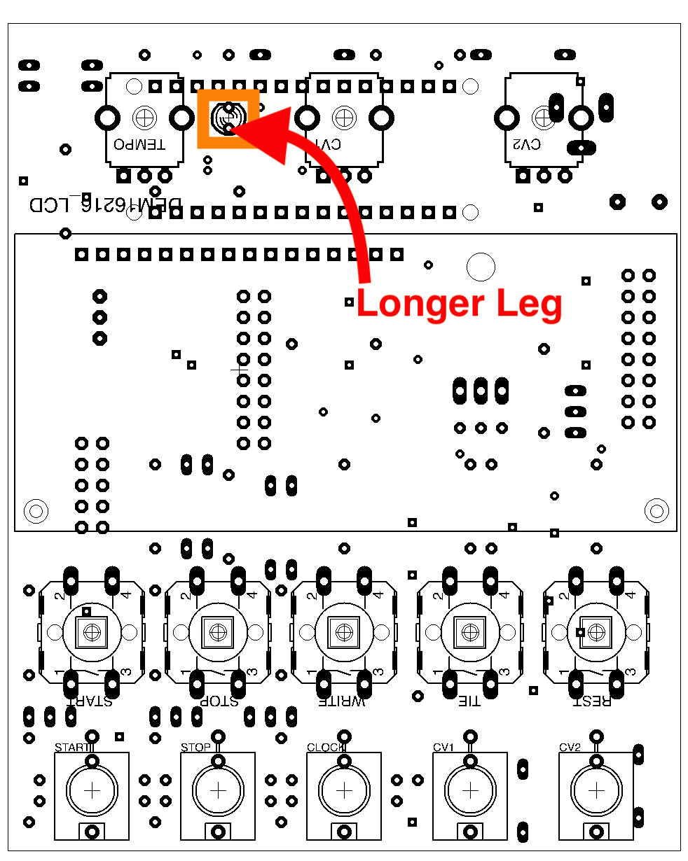
LED and Final Positioning
- Put the LED in place but don't solder it yet. The longer wire must be placed in the lower hole.
- Place the frontpanel on the pcb and fix the potentiometers and the sockets temporarily with their nuts.
- Position the LED in its hole in the front panel and bend its wires slighty aside
- Turn the module on its face
- Solder the LED wires
- Solder the remaining pins of the sockets and the potentiometers.
- Press the knobs on the switches and the potentiometers
Arduino
Seat the arduino in its socket.LCD-Display adjustment
Connect the Arduino Nano with a USB cable to a USB powersupply or your computer. => The display should be lit, but assumingly you will not see anything. Now turn the multiturn trimmer clock wise. It may take ten or more turns until a row of 16 dark rectangles appears: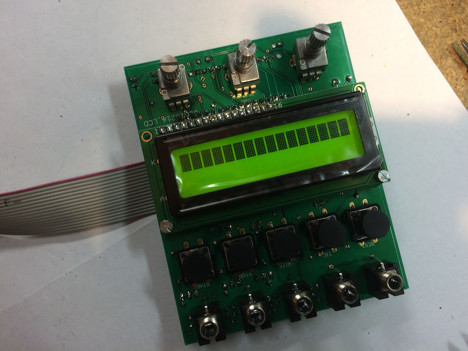
Now turn the trimmer back (= counter clock wise) until the rectangles start to fade out:
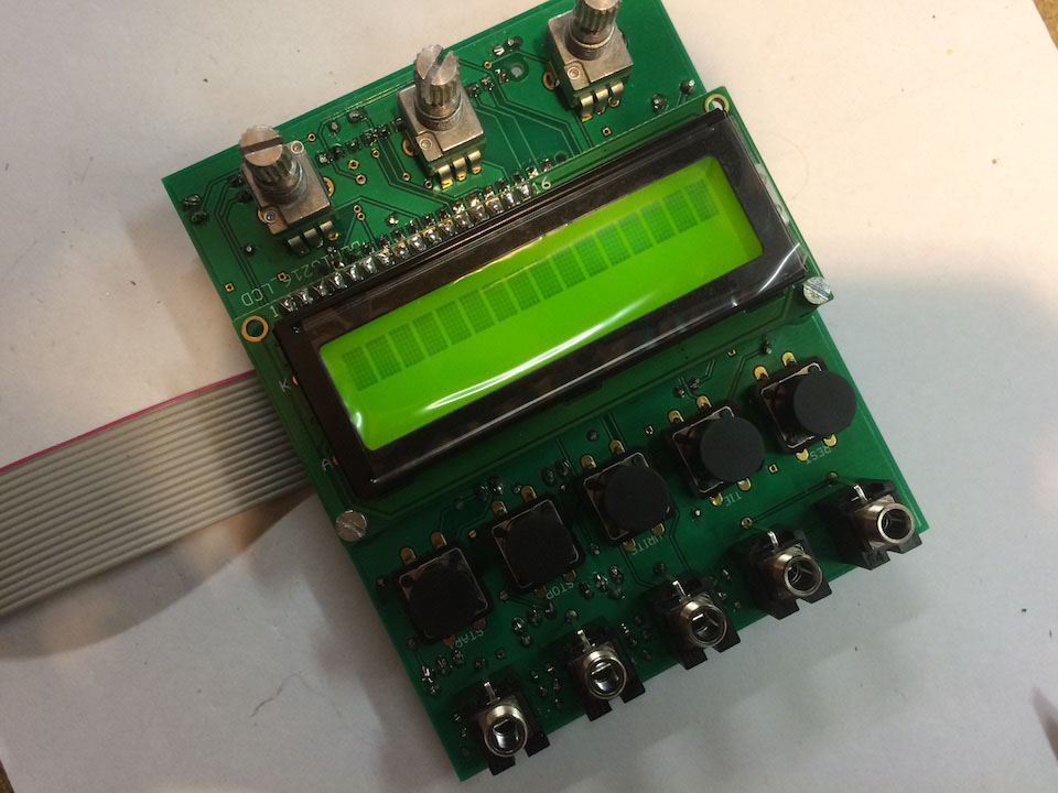
This is a course setting. You may correct this setting after you have loaded software on the Arduino
That's it. You are done.
Now read the VMC-1 programming instructions how to transfer the desired software to the module.
This is a preliminary manual. It is based on prototypes only. Requirements of the final hardware may cause changes in the described use.
All product names and brand names beside "VMC-1", "SQ-3P" and "fanwander" belong to the corresponding owners. They are mentioned only for educational purposes.
All rights reserved, by Florian Anwander 2020 - 2021
\A9 Florian Anwander, 2021 [ imprint/impressum ] [ contact ]