Building
Instructions - MIDI-3IT
!!! PRE RELEASE DRAFT Hardware!!!
This is a preliminary manual. It is based on prototypes only. Requirements of the final hardware may cause changes in the described feature.
Preliminary:
I will not explain soldering. This kit is a little tricky difficult to solder. The order of the soldering is important. Some parts will hide the solder points for other parts. If you mount the parts in the wrong order, you will lock out yourself from finishing the module. Machined precision IC sockets are 100% required. Also I strongly recommend to obey the mounting instructions for the sockets and switches with the help of the frontpanel.Requirements and tools:
- a clean work bench with good illumination
- soldering iron 25W-30W; if possible a soldering station with temperature control
- tin-solder; the PCBs are lead free. Of course lead free tin solder is nice for the environment, but mixed lead/tin-solder is much easier to handle, and it is still allowed to non professionals (at least in the EU)
- an electronic side cutter or microshear like the "Knipex
Electronic
Super
Knips"
- sturdy midsized side cutting pliers
- flat longnose pliers
- a sharp knife or a fretsaw
Not necessary but helpful:
- a "helping hand" pcb holder
- a bending jig made from a strip board pcb:
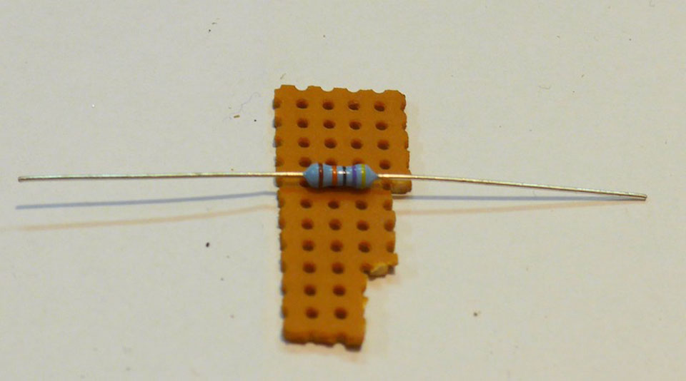
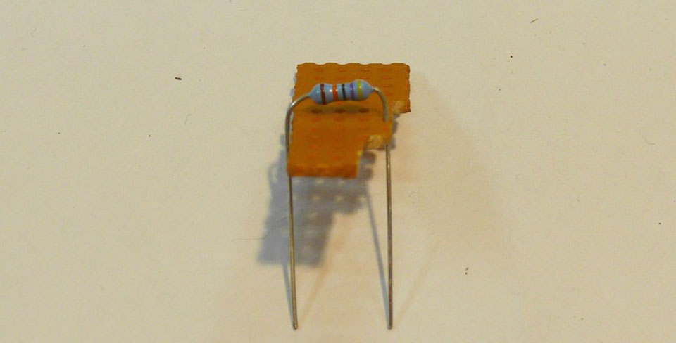
All parts on the pcbs a designed for this standard grid.
Overview:
Basically we will solder parts in the order of their heigth. As mentioned above some parts will hide the solder points for other parts. So keep the following order:- First the rear side.
- diode
- resistors
- IC sockets
- capacitor
- pinhead rows
- Then the front side.
- 3,5mm sockets and DIN-sockets (see remarks in the detail section)
- switches
Details REAR SIDE
Diode:
Observe the right orientation of the diode. There is a black ring mark around the glass body. It must point in the same direction as the corresponding mark on the pcb: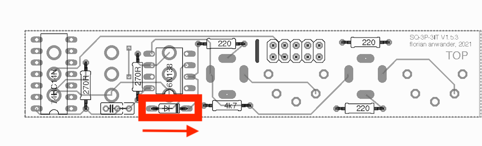
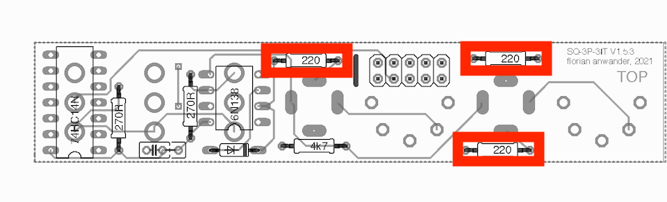
Resistors
The resistors may come in two different physical sizes (0.3W and 0.6W). The wattage does not matter for the functionality. It is simply a question, which size was available while buying. I prefer the larger 0.6W types, but sometimes only the smaller ones are available.220 Ohm:
270 Ohm:
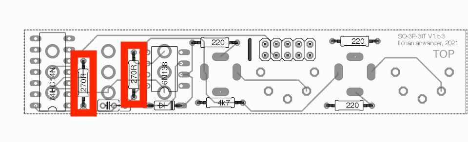
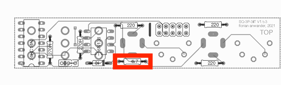
4.7 kOhm:
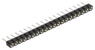
IC sockets:
This is an important advice. Since the solderpoints for the switches are place under the ICs, it is absolutely necessary to use machined precision sockets for the ICs. Cheap standard sockets can not be used!I usually ship SIL-sockets like this with the kit:
If those are not available DIL-Sockets like this one may be used:
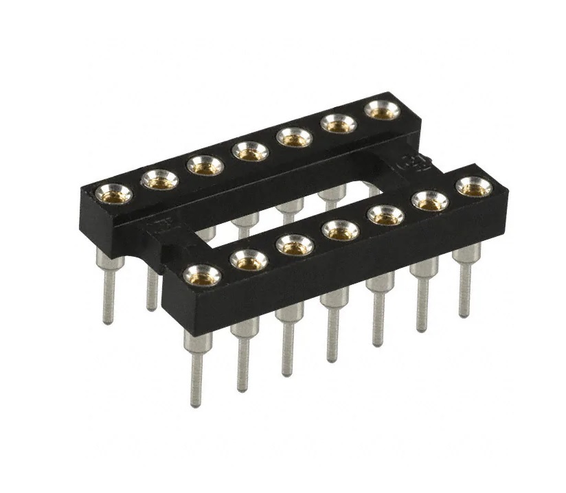
In this case remove the bar, which connects the two contact rows, with a sharp knife or a fret saw. You also may try to cut it with a side cutting plier before you solder it on the pcb.
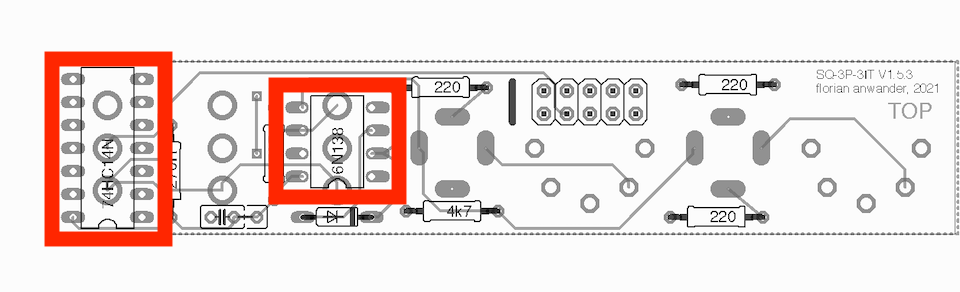
We will place the ICs later in the sockets.
pinheader:
Solder the 2x5 pinheader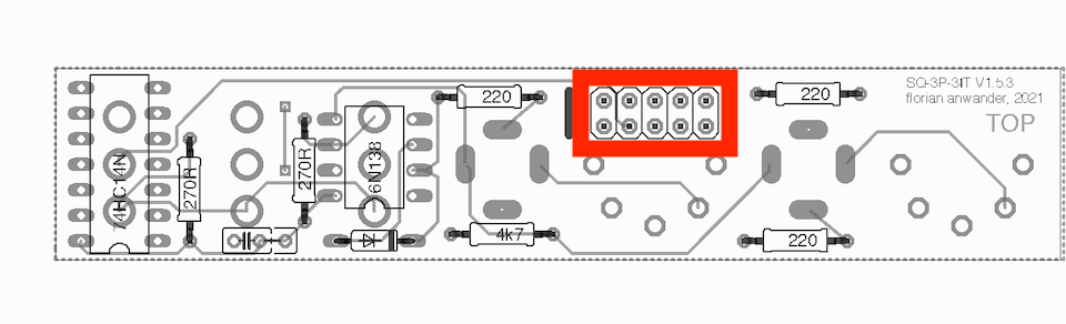
That's it for the rear side!
Details FRONT SIDE
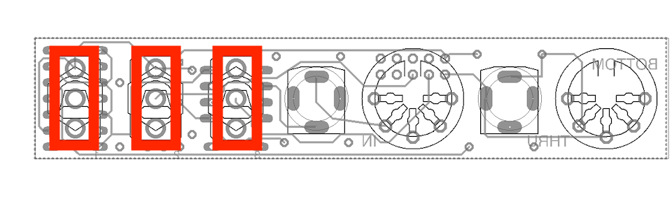
3.5mm Sockets
- Place the 3.5mm sockets on the pcb and solder only one pin of each socket
Switches:
- The switches come with two nuts and two washers on the threaded bushing. Remove the upper nut and the two washers.
- turn the remaining nut to a position, where it has nearly
the same height as the 3.5mm sockets have.
- place
each switches in the corresponding holes and solder the switch on its
center leg. It doesn't have to be a perfect solder joint. We
only want to fix it temporarily for the panel adjustment.
Panel part 1:
- Place the front panel on the pcb and fix the 3.5mm sockets temporarily with their nuts.
- Turn the nuts on the switch bushing so they support the
frontpanel, but the panel shall not be raised by the switches nuts.
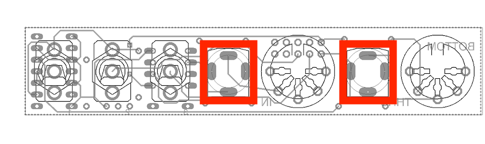
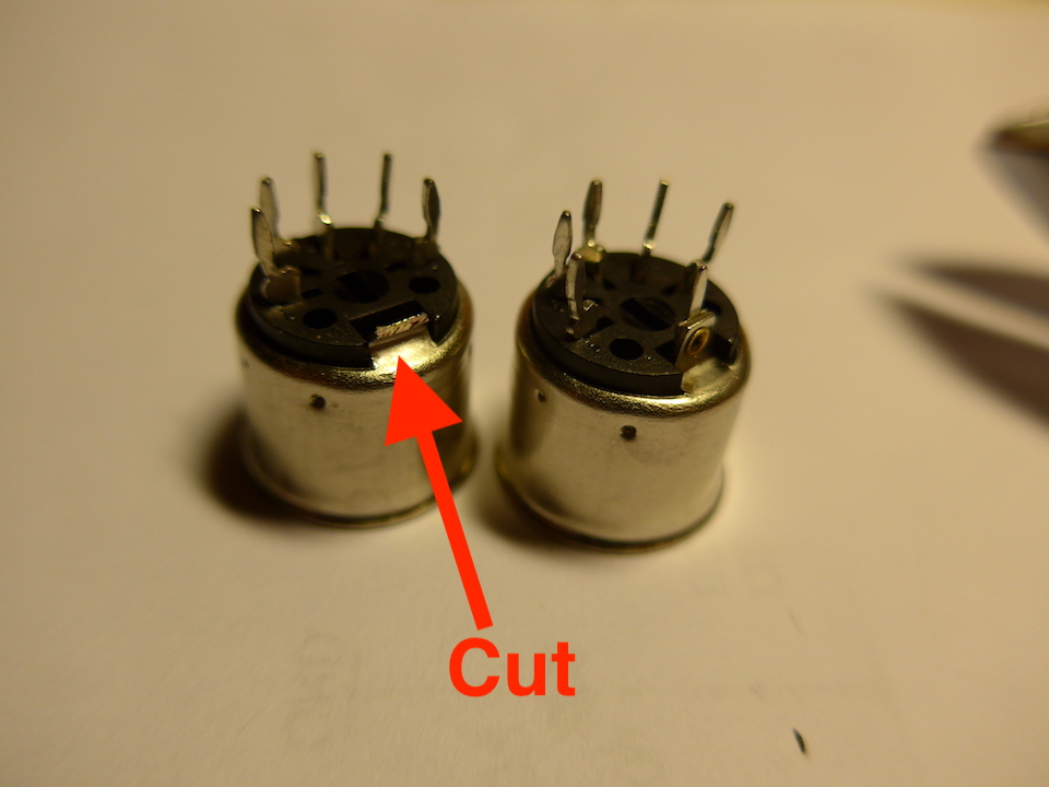
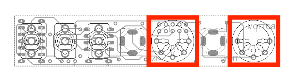
DIN Sockets:
- Cut the ground connector with the side cutting plier from
the three DIN sockets. This requires a really sturdy side cutter.
- Place the DIN sockets from the front thru the panel into their place. They must flush with the panel.
- Put a strip of scotch tape over the frontpanel so the DIN sockets can't fall out
- Solder the DIN sockets and the remaining pins of the 3.5mm sockets
Panel part 2:
- Tighten the nuts of the 3.5mm sockets
- Solder the the switches to their solder points. I recommend
to solder first the inner contact and then the two outer contacts
- Place the flat washer and the nut on the bushing of the switch and turn them down to the front panel; it should not press the panel down. You may now readjust the lower nut again. In the end both nuts should sit fix on the panel (this is the most tricky part in building this module).
ICs:
Insert the ICs into their sockets. Obey the orientation of the ICs. There is a notch which appears also on the pcb printing and/or there is a dot on the IC: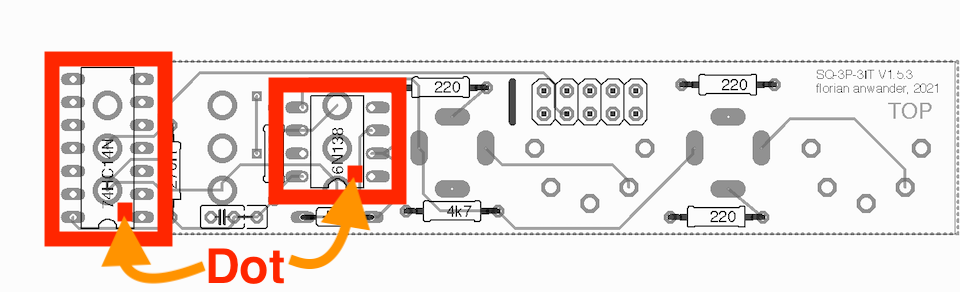
That's it. You are done.
This is a preliminary manual. It is based on prototypes only. Requirements of the final hardware may cause changes in the described use.
All product names and brand names beside "VMC-1", "MIDI-3IT" and "fanwander" belong to the corresponding owners. They are mentioned her only for educational or explaining purposes.
All rights reserved, by Florian Anwander 2020 - 2021