Building
Instructions - MIDI-ITO
!!! PRE RELEASE DRAFT Hardware!!!
This is a preliminary manual. It is based on prototypes only. Requirements of the final hardware may cause changes in the described feature.
Preliminary Remark:
I will not explain soldering. This kit is not really difficult to solder, but I do not recommend it as a first project. The order of the soldering is important. Some parts will hide the solder points for other parts. If you mount the parts in the wrong order, you will lock out yourself from finishing the module. Also I strongly recommend to obey the mounting instructions for the sockets and potentiometers with the help of the frontpanel.Requirements and tools:
- a clean work bench with good illumination
- soldering iron 25W-30W; if possible a soldering station with temperature control
- tin-solder; the PCBs are lead free. Of course lead free tin solder is nice for the environment, but mixed lead/tin-solder is much easier to handle, and it is still allowed to non professionals (at least in the EU)
- electronic side cutter or microshear like the "Knipex Electronic Super Knips"
- midsized side cutting pliers or a very sharp knife like a cardboard cutter
Not necessary but helpful:
- a "helping hand" pcb holder
- adhesive tape ("scotch tape")
- a bending jig made from a strip board pcb:
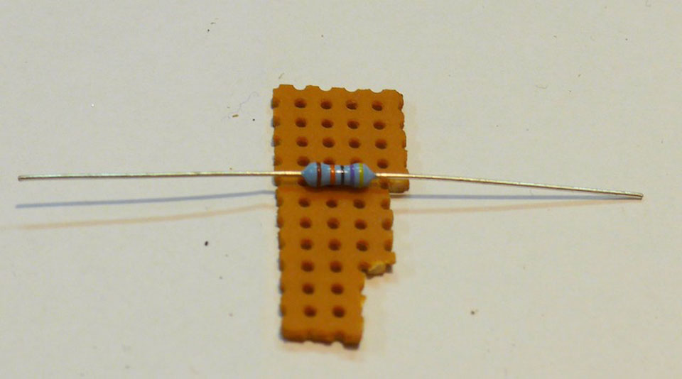
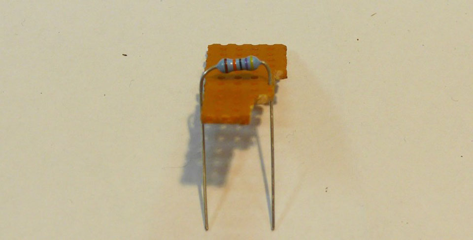
All parts on the pcbs a designed for this standard grid.
Overview:
Basically we will solder parts in the order of their heigth. As mentioned above some parts will hide the solder points for other parts. So keep the following order:- First the rear side.
- resistors and diodes
- IC sockets see remarks in the detail section)
- capacitors
- pinhead rows
- Then the front side.
- 3,5mm sockets and DIN-sockets (see remarks in the detail section)
- display (see remarks in the detail section)
Details REAR SIDE
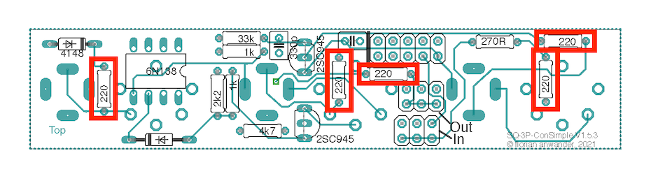
Resistors
The resistors may come in two different physical sizes (0.3W and 0.6W). The wattage does not matter for the functionality. It is simply a question, which size was available while buying. I prefer the larger 0.6W types, but sometimes only the smaller ones are available.220 Ohm:
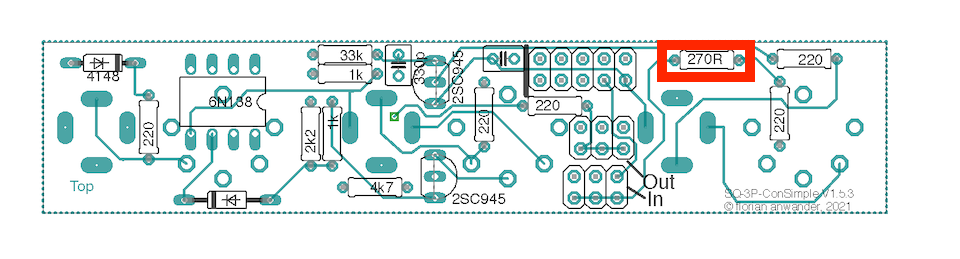
270Ohm:
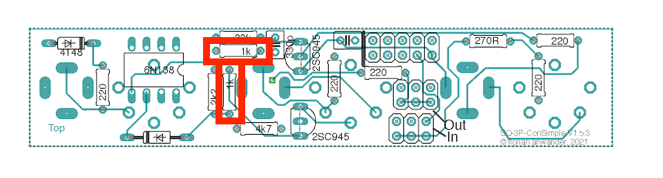
1kOhm:
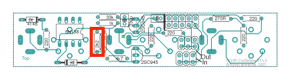
2.2kOhm:
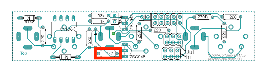
4.7kOhm:
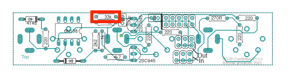
33kOhm:
DIODES
1N4148
Diodes have to be placed in the the right orientation. There is a black ring around the glass body. It must point in the same direction as the black mark is on the pcb diagram. Please obey that the two diodes point in different directions (guess, who steppd into this trap while building the first prototype...).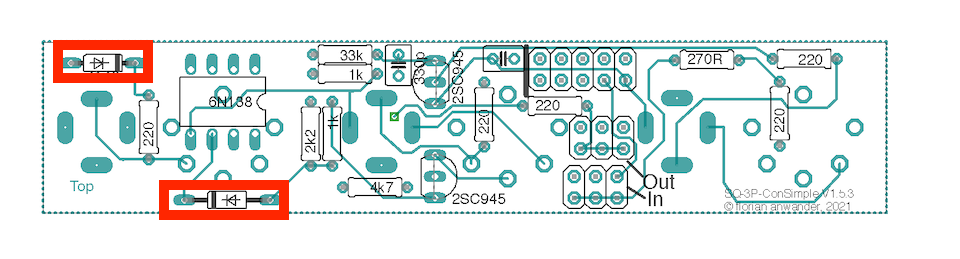
Transistors
2SC945
Keep the orientation of the transistors in mind. On of the two transistors "looks" into a different direction!I recommend to solder the center pin of the transistor first, and then the outer pins.
Capacitors
330p
The 330 picoFarad is brown and round: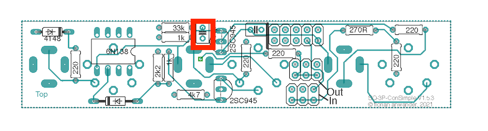
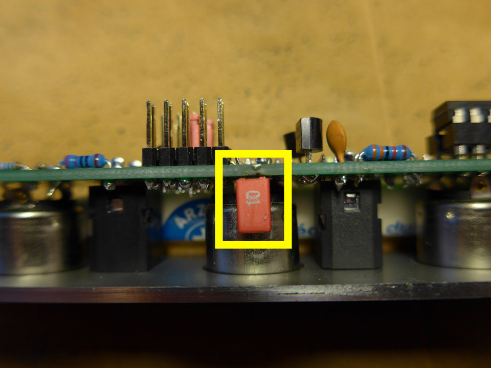
10nF
The 10nF capacitor close to the 2x5 pinheader is printed on the rear side, but it must be mounted on the front side. We will do this later.ICs:
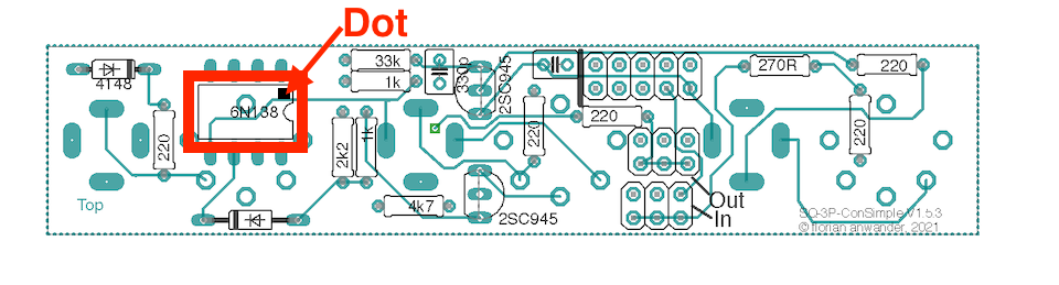
socket and opto coupler:
- Solder the 8pin DIL socket and place the IC on it. Obey the orientation of the IC. There is either a dot or a notch (see marking on the pcb)
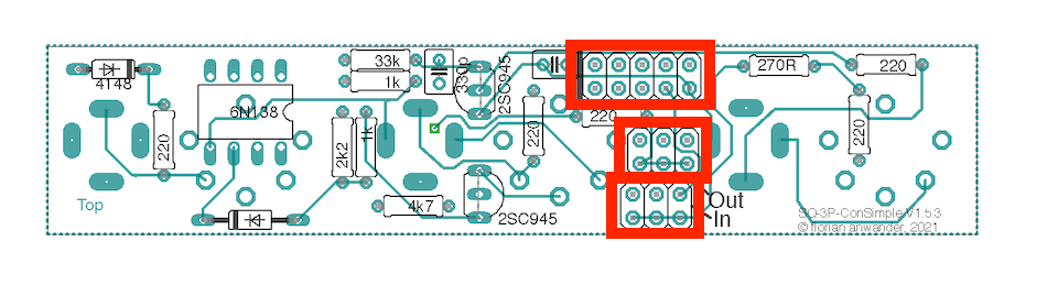
Pinheads:
the pinheads may come as a single part of 2x11. Cut this with the sideplier in two 2x3 pieces and one 2x5 piece.solder those on the pcb
That's it for the rear side!
Details FRONT SIDE
capacitor 10nF
- The 10nF capacitor is printed on the rear side of the pcb, but must be placed on the front side:
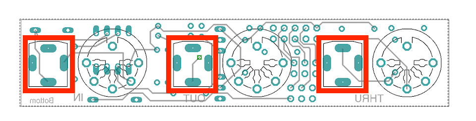
3.5mm Sockets
- Place the sockets on the pcb and solder only one pin of each socket
- Place the frontpanel on the pcb and fix the sockets with their nuts.
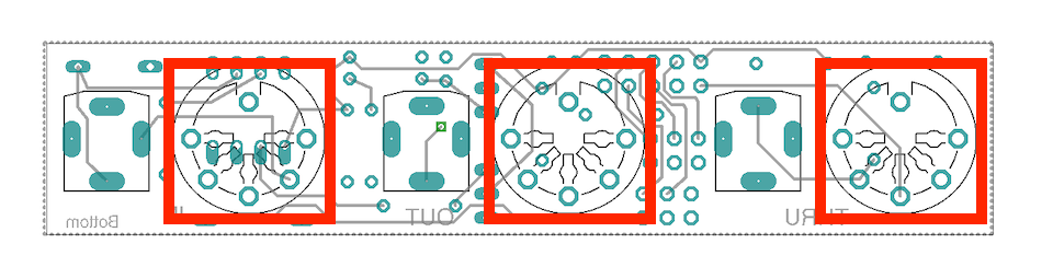
DIN Sockets:
- place the DIN sockets from the front thru the panel into their place. They must flush with the panel.
- put a strip of scotch tape over the frontpanel so the DIN sockets can't fall out
- solder the DIN sockets and the remaining pins of the 3.5mm sockets
- tighten the nuts of the 3.5mm sockets
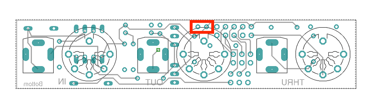
Jumpers
- Place the two jumpers on the 3x2 pinheads. The normal position is the pin pair close to the DIN socket
That's it. You are done.
This is a preliminary manual. It is based on prototypes only. Requirements of the final hardware may cause changes in the described use.
All product names and brand names beside "VMC-1", "MIDI-ITO" and "fanwander" belong to the corresponding owners. They are mentioned her only for educational or explaining purposes.
All rights reserved, by Florian Anwander 2020 - 2021