Users Manual - VMC-System / VMC-1
!!! PRE RELEASE DRAFT Hardware!!!
Features
The VMC-1 is an euro rack module which provides:
- an Arduino Nano board which does all the digital data handling
- a backlit display with 16 characters in two rows. The
display cannot provide graphics.
- five buttons, which are scanned by the Arduino board. The labels are:
- PLAY
- STOP
- WRITE
- F1 (=function 1)
- F2 (=function 2)
- The real function of all those buttons depends on the software loaded to the Arduino
- three potentiometers:
- TEMPO: this potentiometer provides 0 - +5V Volt DC to the Arduino
- CV1: this potentiometer provides the voltage coming from the input CV1 to the Arduino. As the socket CV1 is normalled to +5V the potentiometer will provide 0 - +5V Volt DC to the Arduino if nothing is inserted in the socket.
- CV2: this potentiometer provides the voltage coming from the input CV2 to the Arduino. As the socket CV2 is normalled to +5V the potentiometer will provide 0 - +5V Volt DC to the Arduino if nothing is inserted in the socket.
- five input sockets:
- PLAY: a digital input that executes the same function as the Play button. 0 Volt = button not pressed; 5 - 12 Volt = button is pressed.The usual threshold is around +2V.
- STOP: a digital input that executes the same function as the Stop button. 0 Volt = button not pressed; 5 - 12 Volt = button is pressed. The usual threshold is around +2V.
- CLOCK: a digital input that is read by the Arduino. The switching contact of the socket is connected to a digital output of the arduino. So an external signal can replace a signal which is generated internally by the Arduino. 0 Volt = digital low; 5 - 12 Volt = digital high. The usual threshold is around +2V.
- CV1: a control voltage input that is fed to the potentiometer CV1. The evaluated voltage ranges from 0 Volt to about +5V. The input is limited internally by a Zenerdiode; higher input voltages won't damage the module but will have no effect.
- CV2: a control voltage input that is fed to the potentiometer CV2. The evaluated voltage ranges from 0 Volt to about +5V. The input is limited internally by a Zenerdiode; higher input voltages won't damage the module but will have no effect.
Setting up the module
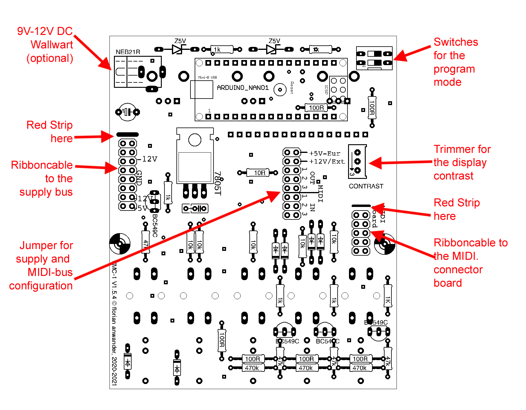
Define the powersupply
As first step you have to define by jumpers which power supply line is used:
- Your eurorack does not provide +5V, so you use the +12V
line:
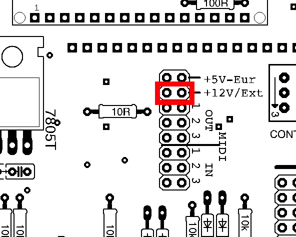
If you use a 9V wallwart powersupply, then you must choose this setting too.
(Wallwart powersupply is only optional available for the kit version).
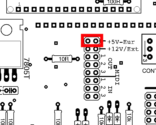
- Your eurorack does provide a +5V line. Then set it like that:
Connection the VMC-1 with the Input/Output-Modules
To be useful the VMC module must be connected to a MIDI-in/out Module like the fanwander MIDI-ITO. The connection is provided by a ten way flat cable, the VMC-bus. The orientation of the cable is important. The cable must be placed with the red strip directing to the marking at the pin header: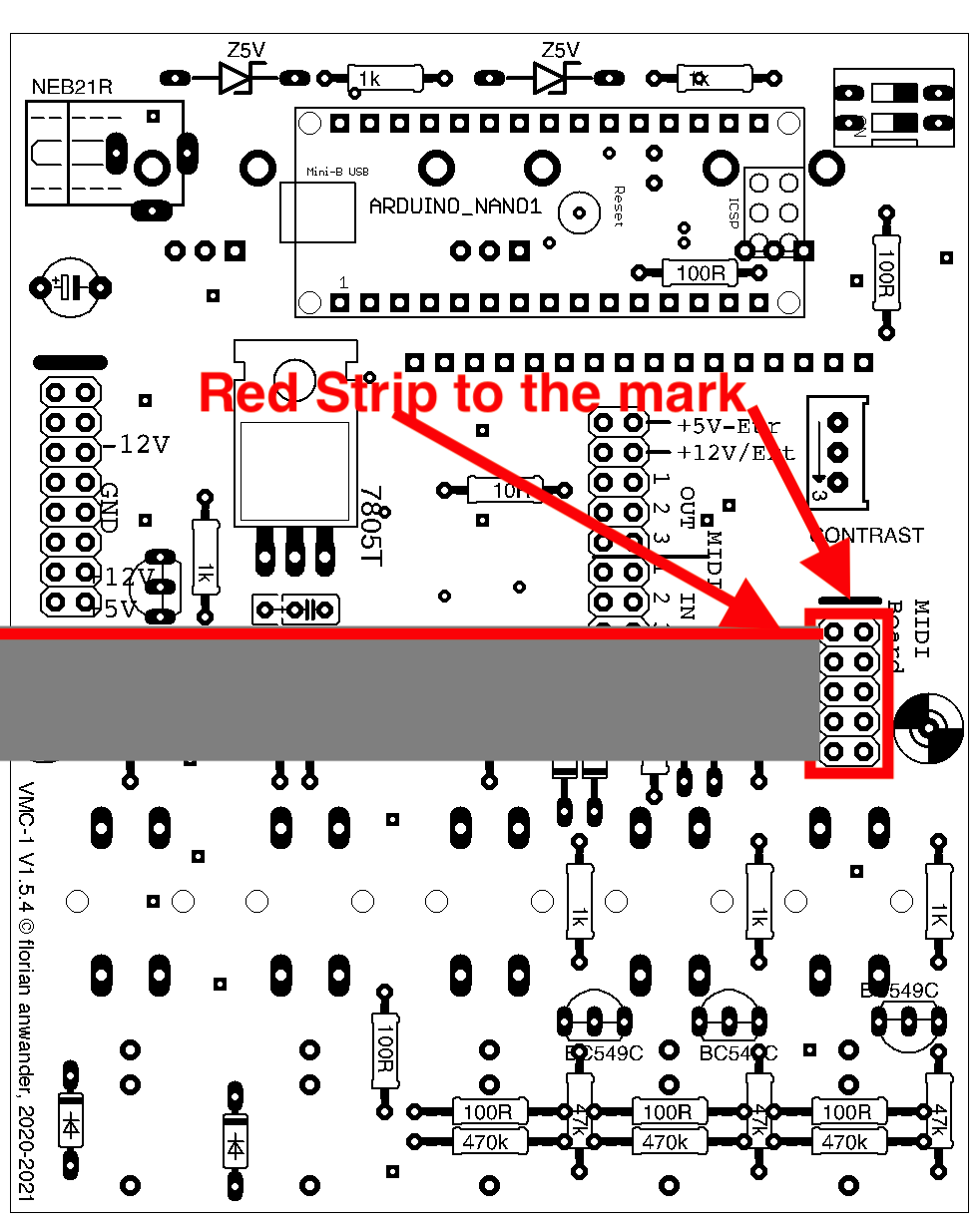
Select the IO configuration
The VMC-Bus provides three busses of MIDI-In/Out. You have to select by jumpers on which bus your VMC-1 module is listening. The standard-setting is "bus 1" for both directions:
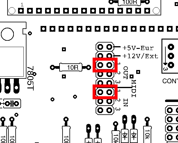 |
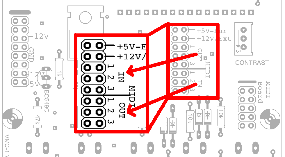
ATTENTION: the labeling for IN and OUT is swapped on the PCB imprint of the first series. The jumpers next to the supply voltage selection are responsible for the MIDI-IN. The jumpers in the direction of the buttons for the MIDI-OUT.
You can recognize the first series by the imprint "VMC-1 V1.5.4 ©florian anwander, 2020-2021". Beginning with version 1.5.5 the labeling is correct.
|
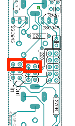
If you use a MIDI-ITO module for the MIDI-connections you have to configure the same bus lines with the jumpers on the MIDI-ITO module:
|
If you use multiport modules like the MIDI-3IT and the MIDI-OOO respectively then no jumper settings are required on those modules.
Connect the VMC-1 with the power supply bus
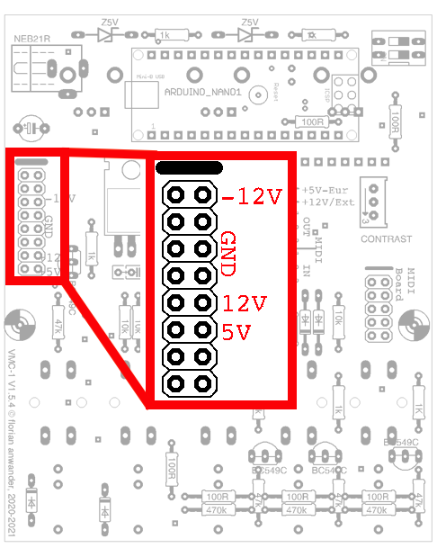
Power off your euro rack system!Connect the VMC-1 with the 16-fold ribbon cable to the supply-bus of your euro rack system. The orientation of the cable is important. The cable must be placed with the red strip directing to the marking at the pin header:
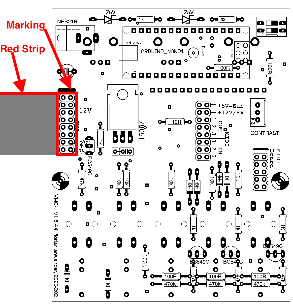
ATTENTION: on the first pcb series, the writing -12/+12/+5 is printed at the wrong position due to an unhappy accident. Don't obey these. The correct pinout is shown below:
This is a preliminary manual. It is based on prototypes only. Requirements of the final hardware may cause changes in the described use.
All product names and brand names beside "VMC-1", "SQ-3P" and "fanwander" belong to the corresponding owners. They are mentioned only for educational purposes.
All rights reserved, by Florian Anwander 2020 - 2021
� Florian Anwander, 2021 [ imprint/impressum ] [ contact ]