Yamaha CS-15 FM Modification
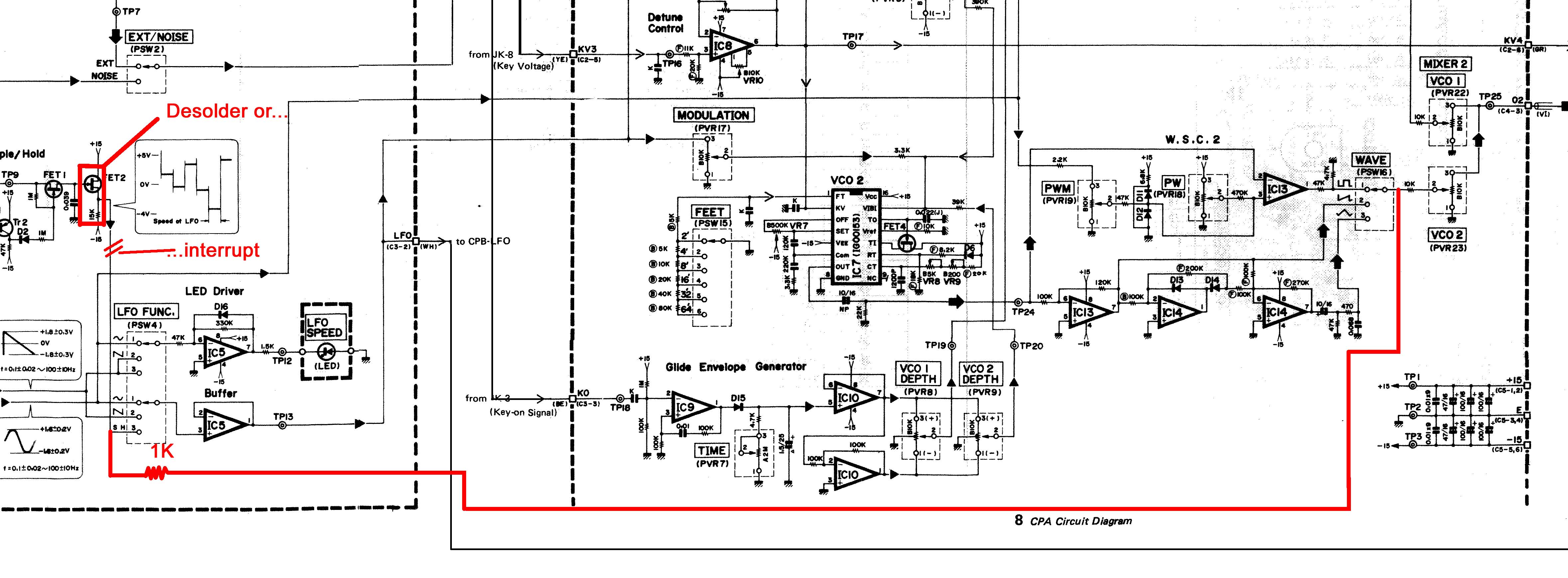
This modification replaces the S&H modulation source by the Output of VCO2. Thus you get FM, filter-FM, and audio-AM. The pulse width modulation will not be affected. The S&H won't be available as modulation source after that mod (I found it never really interesting). There are two ways of disabling the S&H: either interrupt the pcb trace from the S&H-circuit to the LFO waveform switch, or by desoldering FET2 and the 15k resistor close to it. The advantage of the first version is, that you do not have to remove the frontpanel pcb. Its disadvantage is, that removing the modification requires to repair this "broken" trace.
Simple version (but not so nice to remove):- Open the lid removing two screws at each side panel as described in the service manual
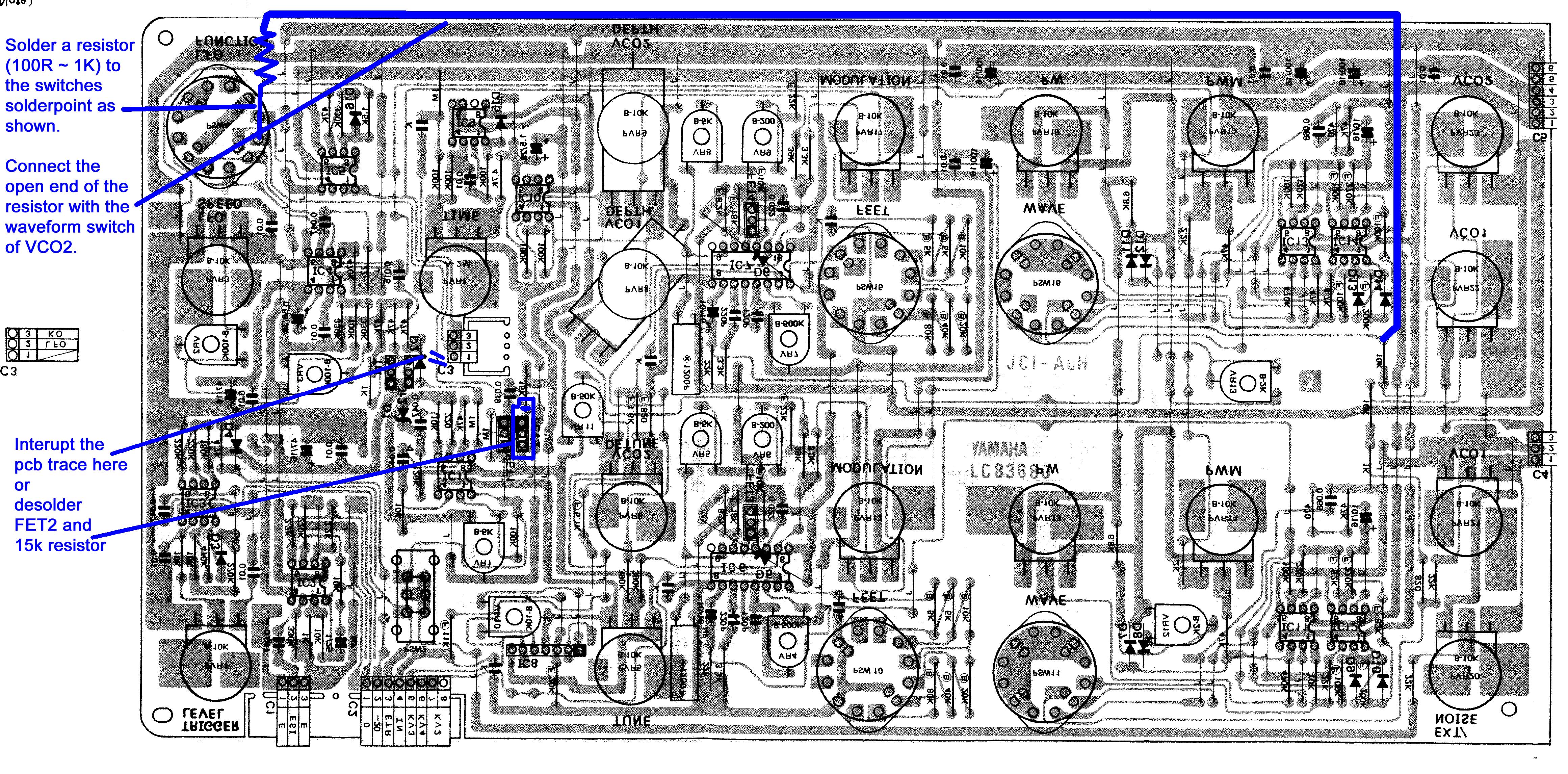
- cut the trace from FET2 to the LFOs waveform switch as shown in the image of the pcb below
- solder a resistor to the solder point at the LFOs waveform switch as shown in the image of the pcb below
- solder a wire to the open end of the resistor, and the other end of the wire to the solder point of the 10k resistor at the right hand side
- Close the lid and remount the screws
- Pull all potentiometer / switch knobs from the left side of the panel up to the mixer potentiometers (incl.)
- Remove all hexnuts from the potentiometers / switches, but leave the nut of VCO1 modulation still at its place (it must not be fixed completely, but it still must hold the pcb). Pay attention: the nuts of the potentiometers have a different diameter than the nuts from the rotating switches!
- Open the lid removing two screws at each side panel as described in the service manual.
- Desolder the black and red wire at the left side of the panel pcb (those feed the LFO LED).
- Now close the lid again, with one hand inside, that will hold the pcb
- Remove the last hex nut from the potentiometer -> the pcb now will fall in your hands
- Open the lid again: all potentiometers /switches have washers with exception of the left row, which is covered by a metal frame. Remove the washers and the metal frame (again the switches have slightly larger washers than the potentiometers.
- Now desolder FET2 completely and remove the 15k resistor close to FET2 - at least desolder and lift it from the solder point close to FET2. See the the image of the pcb below
- Solder a resistor to the solder point at the LFOs waveform switch as shown in the image of the pcb below
- Solder a wire to the open end of the resistor, and the other end of the wire to the solder point of the 10k resistor at the right hand side
- Put the washers on the potentiometers again. Same with the metal frame on the left row of potentiometers. Take care that the red and black wire from the LED peek out from the metalframe.
- Place the pcb on one hand so the washers cannot fall from the potentiometers.
- Prepare one of the hex nuts for a potentiometer in reach.
- Close the panel, align the pcb into the holes on the frontpanel, grab the nut and fix the pcb with the VCO1 mod potentiometer on the frontpanel
- Add all other nuts
- Resolder the red and black cable from the LED. The solder points are marked with "BL" and "RD"
- Close the lid and remount the screws
The modification in the schematics:

The modification on the pcb:

The image shows the pcb as seen when the panel is opened up, but the pcb still is mounted to the panel.
© Florian Anwander, 2019 [ imprint/impressum ] [ contact ]